
Method for determining the contributions of individual transmission paths

a transmission path and individual technology, applied in the direction of instruments, pressure difference measurement between multiple valves, inflated body pressure measurement, etc., can solve the problems of sensitivity function and inertance errors, and achieve the effect of rapid and accurate computation of forces

Inactive Publication Date: 2009-08-13
AVL LIST GMBH
View PDF0 Cites 12 Cited by
  • Summary
  • Abstract
  • Description
  • Claims
  • Application Information

AI Technical Summary

Benefits of technology

[0004]It is the object of the present invention to avoid the above mentioned disadvantages and to propose a method for rapid and accurate computation of forces and of the contributions of individual transmission paths to total noise.
[0017]A substantial improvement of the computed results is obtained if the excitation of all sources is taken into account by measuring accelerations or sound pressures near all defined sound input positions. Neglecting even one important sound source would lead to erroneous sensitivity functions and inertances. Additionally it is assumed that the acceleration-to-sound pressure respectively acceleration-to-acceleration sensitivity functions are time-invariant for all measurements in the operational state. Since positions and directions of the acceleration sensors are constant, the assumption implies that the temperature of the structure (e.g. the body of a vehicle) is to be kept as constant as possible for measurements in the operational state. Preheating the structure prior to measurement is therefore advantageous.
[0018]When sound transmission in air is present, the quality of the measurement results will improve if pressure-to-pressure or pressure-to-acceleration sensitivity functions are determined for the total air-borne sound between sound input positions and receiving positions, and if the contributions of air-borne sound to the total sound pressure or total acceleration at the receiving position is determined from pressure-to-pressure or pressure-to-acceleration sensitivity functions and the sound pressure measured during operation at the sound input positions, and if the contribution of air-borne sound is subtracted from the total sound pressure or the total acceleration at the receiving position.
[0021]The method of the invention permits computation of inertances from measurements during operation and from the reciprocally measured frequency response functions between sound input position and receiving position. The advantages of the proposed new method are to be found in the significant reduction of time needed and in the avoidance of errors generally arising in the measurement of inertances or frequency responses. While the time-saving aspect of the method is obvious, the improvement in measurement quality will be further described in the following.
[0027]The use of reciprocally measured frequency response functions will eliminate deviations in the direction of excitation since the force direction for the measured frequency response functions is identical with the measuring direction of the acceleration sensor. Furthermore, when measuring inertances and frequency response functions, it is easier to position an acceleration sensor near the origin of the excitation sources than to place a shaker or hammer at this site for external excitation. The error which is due to deviation from the sound input position, will thus be reduced by the present method.
[0028]The error due to temperature differences is reduced by reciprocal measurement if reciprocal measurement of the frequency response functions between sound input position and receiving position is carried out immediately after the operative measurement of sound pressure and sound acceleration. This will eliminate problems due to differing temperatures at the operative measurement and at the inertance or frequency response measurement.

Problems solved by technology

Neglecting even one important sound source would lead to erroneous sensitivity functions and inertances.

Method used


Image

  • Method for determining the contributions of individual transmission paths
  • Method for determining the contributions of individual transmission paths
  • Method for determining the contributions of individual transmission paths

Examples


Embodiment Construction

[0038]The invention will now be explained in more detail with reference to an example.

[0039]To enable deeper understanding of the method of the invention a stepwise description of the theory will now be given. To reduce complexity the example below contains only receiving positions for air-borne sound in the cabin. Thus the computations involve only sound pressure and no accelerations at the receiving positions. Computation with accelerations could be carried out identically. If both accelerations and sound pressures at the receiving positions are to be used scaling of the matrices should be considered.

[0040]For more detailed explanation sound pressure ptot at the target microphone may be split into a structure-borne component pSB and an air-borne component pAB, as shown in equation (1):

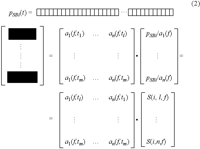
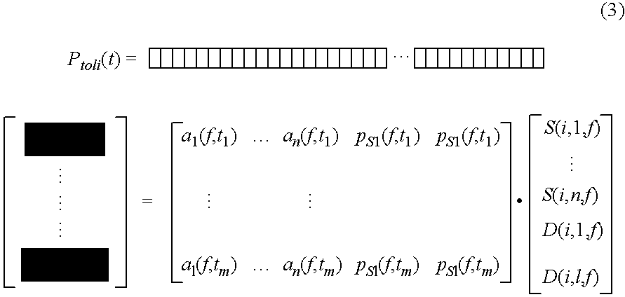
ptot=pSB+PAB   (1)[0041]ptot . . . total sound pressure[0042]pSB . . . structure-borne part of sound pressure[0043]pAB . . . air-borne part of sound pressure

[0044]Step 1.1—Determination of the Accele...


PUM


Abstract

A method for determining the contributions of individual sound transmission paths to the operation-dependent total noise of a sound transmitting structure includes the following steps:applying at least one acceleration sensor and / or source microphone in the area of each sound input position;applying at least one target microphone and / or acceleration sensor in the area of a receiving position;carrying out at least one simultaneous measurement of sound pressure and / or acceleration at the receiving position and of acceleration and / or sound pressure at each sound input position during operation;determining at least one acceleration-to-pressure and / or acceleration-to-acceleration sensitivity function and / or at least one pressure-to-pressure sensitivity function;determining reciprocally measured frequency response functions between each sound input position and each receiving position;determining the inertances in the operational state for at least one sound input position;determining of at least one force at at least one sound input position based on the computed inertances and the accelerations measured during operation at the sound input positions; anddetermining the contributions of the individual transmission paths.

Description

BACKGROUND OF THE INVENTION[0001]The invention relates to a method for determining the contributions of individual transmission paths to the total operation-dependent noise of a sound transmitting structure, in particular a vehicle.[0002]Vibration or force input and transmission in a sound-transmitting structure, as for instance a vehicle body, is usually analyzed by a method known as “Transfer Path Analysis” (TPA). In this method the input inertances for certain force input points on the body and the transfer functions from these force input points to microphones in the vehicle interior and / or to vibration measuring points on the body are determined with the use of external excitation (shakers, hammers etc.). The effects of real excitations on the vehicle body during operation of the vehicle are determined by measuring accelerations at the force input points during operation and applying the previously determined inertances and transfer functions. The measurement of inertances and ...

Claims


Application Information

Patent Timeline
IPC IPC(8): G06F15/00G01P15/00
CPCG01H3/08G01H1/00
Inventor HOELDRICH, ROBERTSONTACCHI, ALOISBRANDL, STEPHAN
Owner AVL LIST GMBH
Learn More