Image forming apparatus
a technology of forming apparatus and forming roller, which is applied in the direction of electrographic process apparatus, instruments, optics, etc., can solve the problems of uneven transfer, uneven transfer, uneven transfer, etc., and achieve the effect of suppressing the increase in drive torque of the belt and reducing friction for
- Summary
- Abstract
- Description
- Claims
- Application Information
AI Technical Summary
Benefits of technology
Problems solved by technology
Method used
Image
Examples
embodiment 1
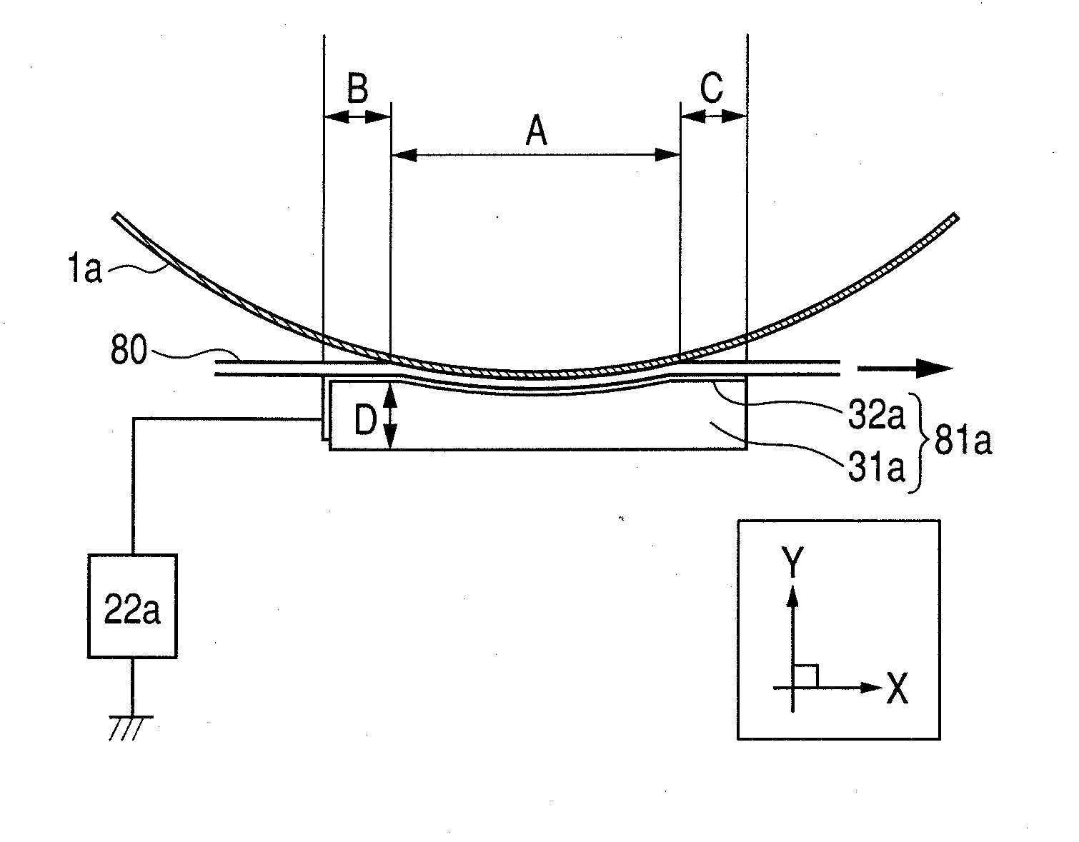
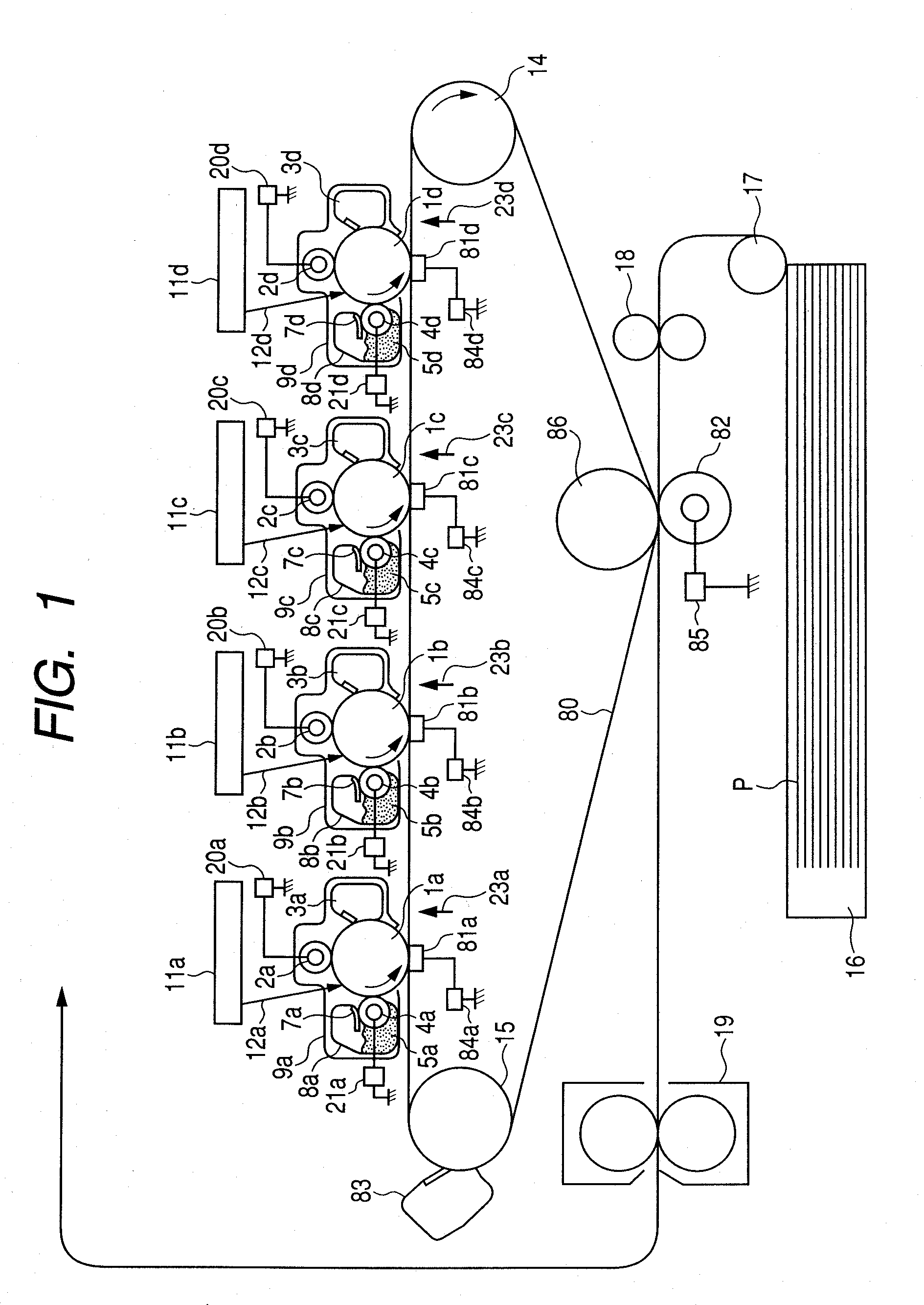
[0030]Embodiment 1 of the present invention is now described with reference to the drawings. FIG. 1 is a schematic view illustrating an overall configuration of an image forming apparatus. Here, as the image forming apparatus of Embodiment 1, a color printer including multiple image forming portions (image forming stations) is described by way of example.
[0031]The image forming apparatus illustrated in FIG. 1 includes four image forming stations which can form toner images of different colors. Here, a first image forming station is for yellow (a), a second image forming station is for magenta (b), a third image forming station is for cyan (c), and a fourth image forming station is for black (d).
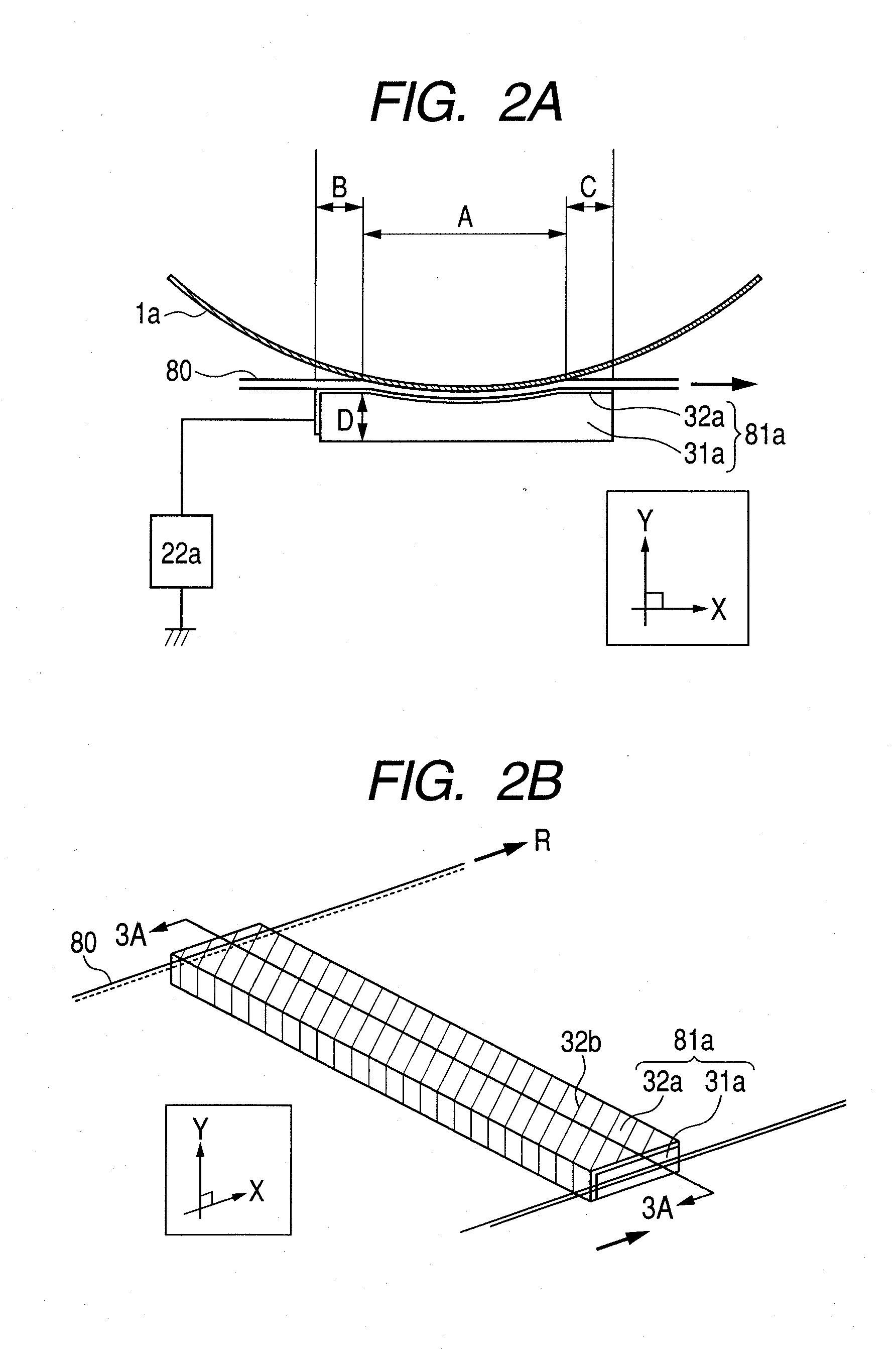
[0032]Process cartridges 9a, 9b, 9c, and 9d corresponding to the respective colors are detachably attached to the respective image forming stations. The process cartridges 9a, 9b, 9c, and 9d have substantially the same configuration. Each of the process cartridges 9 includes a photosensitive ...
embodiment
Evaluation of Embodiment
[0059]In order to study the effects of the primary transfer portion according to Embodiment 1, an image forming apparatus having a process speed of 50 mm / sec was used to make evaluations with regard to the friction co-efficient of the sheet member, the drive torque of the belt, and the vertical thin line-like transfer failure due to contact unevenness in the longitudinal direction, utilizing comparative examples described in the following.
[0060]It is to be noted that, in the respective comparative examples described in the following, the first image forming portion is described, but the second to fourth image forming portions are configured similarly to the first image forming portion, and thus, description thereof is omitted.
embodiment 2
Evaluation of Embodiment 2
[0088]As an abbreviated method of evaluating the effect of decreasing friction force and adsorptive force which act between the transfer member 81a and the intermediate transfer belt 80 of this embodiment, the following was carried out.
[0089]As illustrated in FIG. 12, the intermediate transfer belt 80 was stuck on a support 92 which is grounded so that there is no gap therebetween, and the transfer member 81a is disposed thereon so that the sheet member 32a is brought into contact with the surface of the intermediate transfer belt 80. Further, the transfer member 81a is pressed against the intermediate transfer belt 80 with pressure which correspond to that applied in the image forming apparatus. The transfer member 81a is disposed so that an arbitrary voltage is applied thereto by an external power supply device 90. Further, a digital force gauge 91 is attached to the transfer member 81a so that, when the transfer member 81a horizontally moves on the inter...
PUM
 Abstract
Description
Claims
Application Information
 - R&D
- Intellectual Property
- Life Sciences
- Materials
- Tech Scout
- Unparalleled Data Quality
- Higher Quality Content
- 60% Fewer Hallucinations
Browse by: Latest US Patents, China's latest patents, Technical Efficacy Thesaurus, Application Domain, Technology Topic, Popular Technical Reports.
© 2025 PatSnap. All rights reserved.Legal|Privacy policy|Modern Slavery Act Transparency Statement|Sitemap|About US| Contact US: help@patsnap.com


