RFID tag with user-controlled kill mechanism

a user-controlled, tag technology, applied in the direction of electrical equipment, memory record carrier reading problems, indirect connection of subscribers, etc., can solve the problems of no practical way to alter a barcode label, rfid tag does not automatically stop working, and consumers are less enthusiastic about the proliferation of rfid technology

Inactive Publication Date: 2009-08-13
IBM CORP
View PDF7 Cites 1 Cited by
  • Summary
  • Abstract
  • Description
  • Claims
  • Application Information

AI Technical Summary

Benefits of technology

[0015]FIG. 2 is a more detailed representation of one type of RFID tag in which the present invention may be implemented.
[0016]FIG. 3 is a more detailed representation of another type of RFID tag in which the present invention may be implemented.

Problems solved by technology

There is no practical way to alter a barcode label.
While manufacturers, wholesalers and retailers have responded favorably to the use of RFID tags, some consumers have been less enthusiastic about the proliferation of RFID technology.
The problem is that an RFID tag does not automatically stop working simply because a consumer purchases the product to which the tag is affixed.
Consumers are uneasy because the continued readability of RFID tags, by tag readers that may be located at considerable distances from the tags, creates the potential for unscrupulous people to learn what products a consumer is using without the consumer's permission or even without the consumer's knowledge.
In general, some consumers fear that RFID technology may be used in ways that amount to a breach of the consumers' expectation of privacy.
A problem with this solution is that there are legitimate post-purchase uses for RFID tags, including use if the consumer returns the product for servicing.
Moreover, disabling an RFID tag at the point of sale isn't a realistic option where the product is shipped to the consumer following an Internet or other on-line sale.
As a result, considerable work has been done to increase the durability of RFID tags, which makes it more difficult for consumers to physically destroy them without risking damage to the product to which the tag is affixed.

Method used


Image

  • RFID tag with user-controlled kill mechanism
  • RFID tag with user-controlled kill mechanism
  • RFID tag with user-controlled kill mechanism

Examples


Embodiment Construction

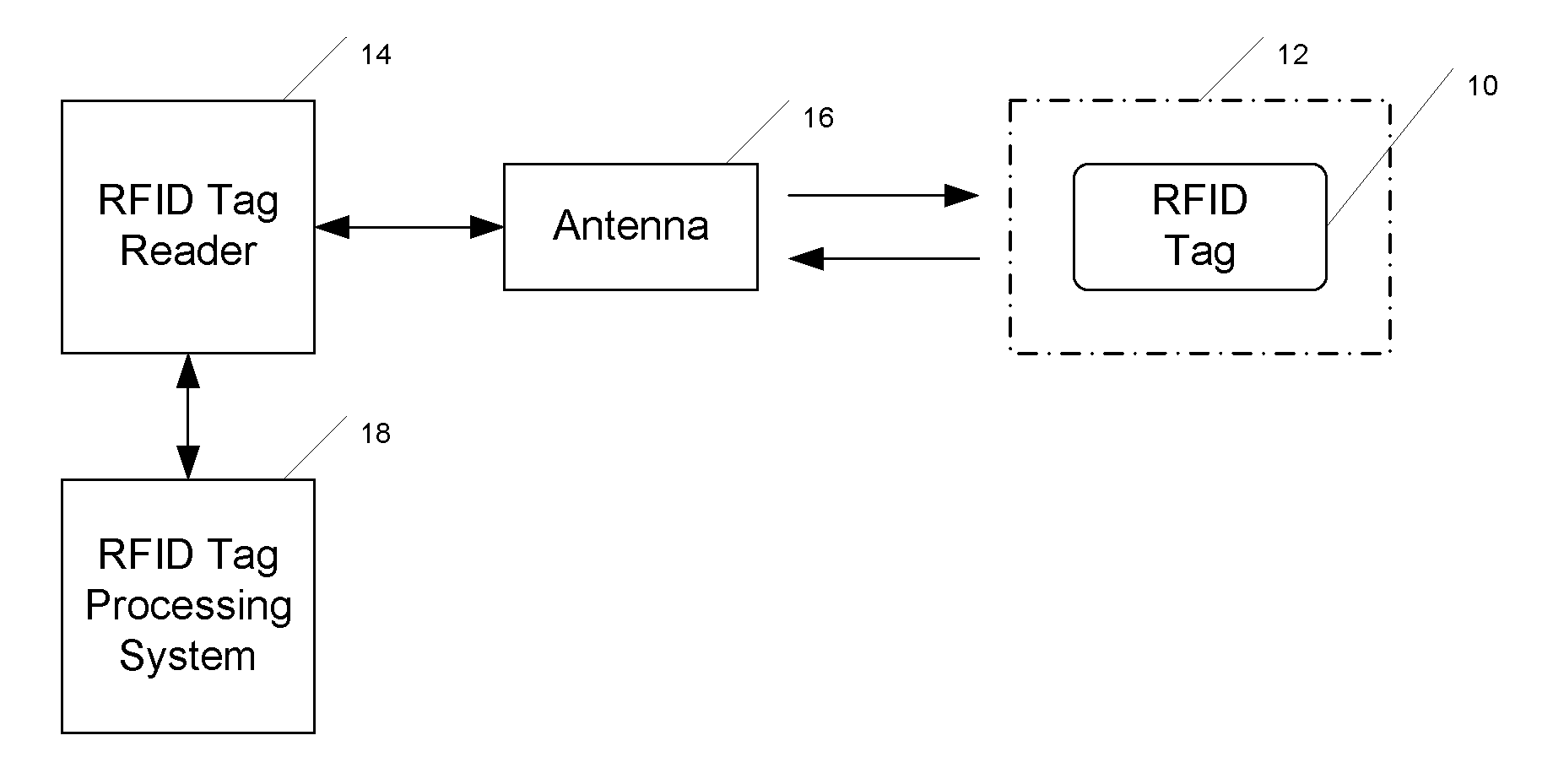
[0021]FIG. 1 shows an RFID tag 10 affixed to the surface 12 of a product or other object (not otherwise shown in the drawing). As noted earlier, the RFID tag 10 carries coded data relevant to the product or object with which it is used. As one example, if the RFID tag is being used with a consumer product, the tag may carry product information such as model number, serial number, etc. As another example, if the tag is integrated into a chip injected under the skin of a pet, the tag may carry an ID number that can be associated with contact information for the pet's owner.

[0022]The coded information stored in an RFID tag is recovered by a tag reader system that includes an RFID tag reader device 14 and an antenna 16. Where the RFID tag is passive or semi-passive, the antenna 16 broadcasts an RF interrogation signal that is received by the RFID tag. The RFID tag responds by broadcasting coded information back through the antenna 16 to the RFID tag reader 14. The acquired information i...


PUM


Abstract

An inexpensive disabling or kill mechanism is provided for an RFID tag to allow a user to decide when to disable the tag and to initiate the kill process. RFID tag antenna circuitry is partially or wholly covered with an oxidation-retardant coating. The activation-retardant coating includes a grippable pull tab. When a user decides he or she no longer wants a functional RFID tag, the user can use the pull tab to remove the least a selectable area of the oxidation-retardant coating. Removing the selectable area will expose at least part of the antenna to begin an oxidizing process that will eventually disable the antenna. An oxidizing agent may be deposited on the antenna before the oxidation-retardant coating is put in place. When exposed to ambient environment, the oxidizing agent may accelerate the oxidation process that disables the antenna.

Description

BACKGROUND OF THE INVENTION[0001]The present invention relates to RFID (Radio Frequency IDentification) technology and more particularly to an RFID tag structure with a user-controlled kill mechanism.[0002]The term RFID is applied to technologies that use radio waves to identify people or objects. More specifically, the people or objects are identified by attached RFID tags that are interrogated by reader devices to retrieve coded information stored in the tags.[0003]There are different types of RFID tags. A passive RFID tag includes an antenna and an integrated circuit module for storing object identification data but has no “onboard” power source. As will be explained in more detail below, a passive RFID tag derives the power it needs to activate the integrated circuit module from radio frequency energy contained in an interrogation signal generated by a tag reader device.[0004]An active RFID tag similarly includes an antenna and an integrated circuit module for storing object ide...

Claims


Application Information

Patent Timeline
Patent Type & Authority Applications(United States)
IPC IPC(8): H04Q5/22
CPCG06K7/0008
Inventor GREENLEE, KENNETH L.HUNT, CHRISTIAN LEERYAN, ANNE IRENE
Owner IBM CORP
Why Eureka
Try Eureka