
Icing protection for aircraft air inlet scoops

a technology for air intake scoops and aircraft, which is applied to aircraft power plants, aircraft components, ground installations, etc., can solve the problems of severe ice accumulation on airframe components, disruption of engine air flow, and aircraft performance degradation

Active Publication Date: 2009-08-06
EMBRAER SA
View PDF5 Cites 17 Cited by
  • Summary
  • Abstract
  • Description
  • Claims
  • Application Information

AI Technical Summary

Benefits of technology

The patent text describes an icing protection system for aircraft air scoops that uses residual heat energy from heated air discharged from the engine. The system includes an air duct with air inlet and outlet openings, a fairing that covers the air duct and defines an interior fairing space, and a tube that connects the interior fairing space to the engine nacelle. The heated air flows through the tube to the interior fairing space to provide icing protection to the air scoop. The system can also include an air scoop with a fairing over a portion of the air inlet duct to further prevent ice formation. The technical effect of this system is to provide better protection against ice formation on airframe components, preventing damage and ensuring safe flight.

Problems solved by technology

If left unchallenged, ice accretion on airframe components severely degrades aircraft performance, for example, by degrading the aerodymanic characteristics of lift surfaces, disruption of engine air flow and blockage of cooling air inlets and the like.

Method used


Image

  • Icing protection for aircraft air inlet scoops
  • Icing protection for aircraft air inlet scoops
  • Icing protection for aircraft air inlet scoops

Examples


Embodiment Construction

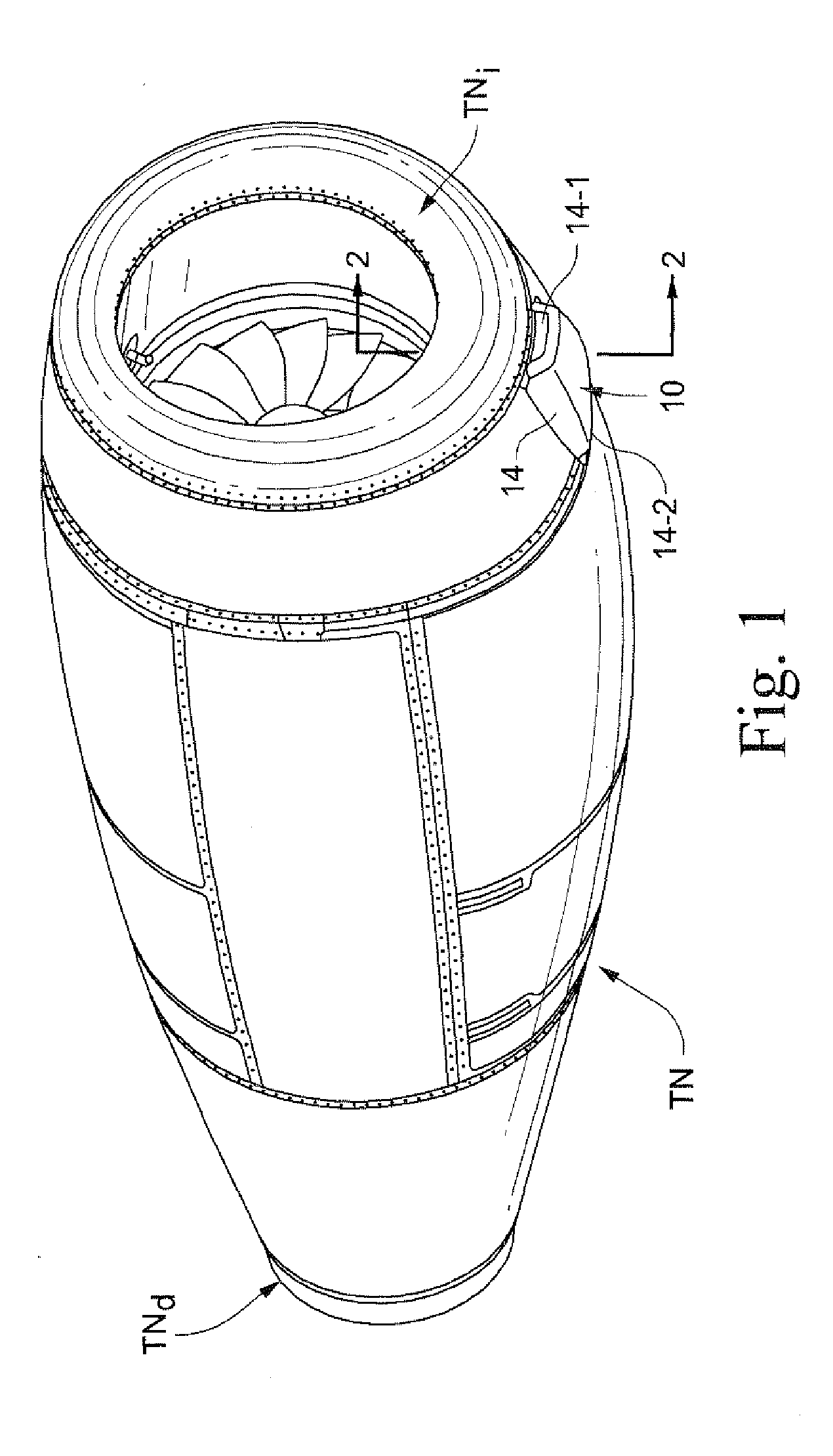
[0016]Accompanying FIG. 1 depicts a turbofan nacelle TN having a forward air inlet lip TNi and a rearward thrust discharge end TNd. The nacelle TN is adapted to being supported by an airframe structure, such as the aircraft wings or fuselage, so that the engine can provide unobstructed thrust for aircraft propulsion when operated. A ram air scoop 10 is positioned adjacent the nacelle inlet lip TNi.

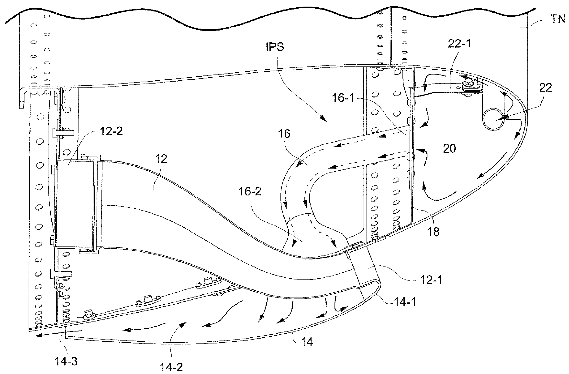
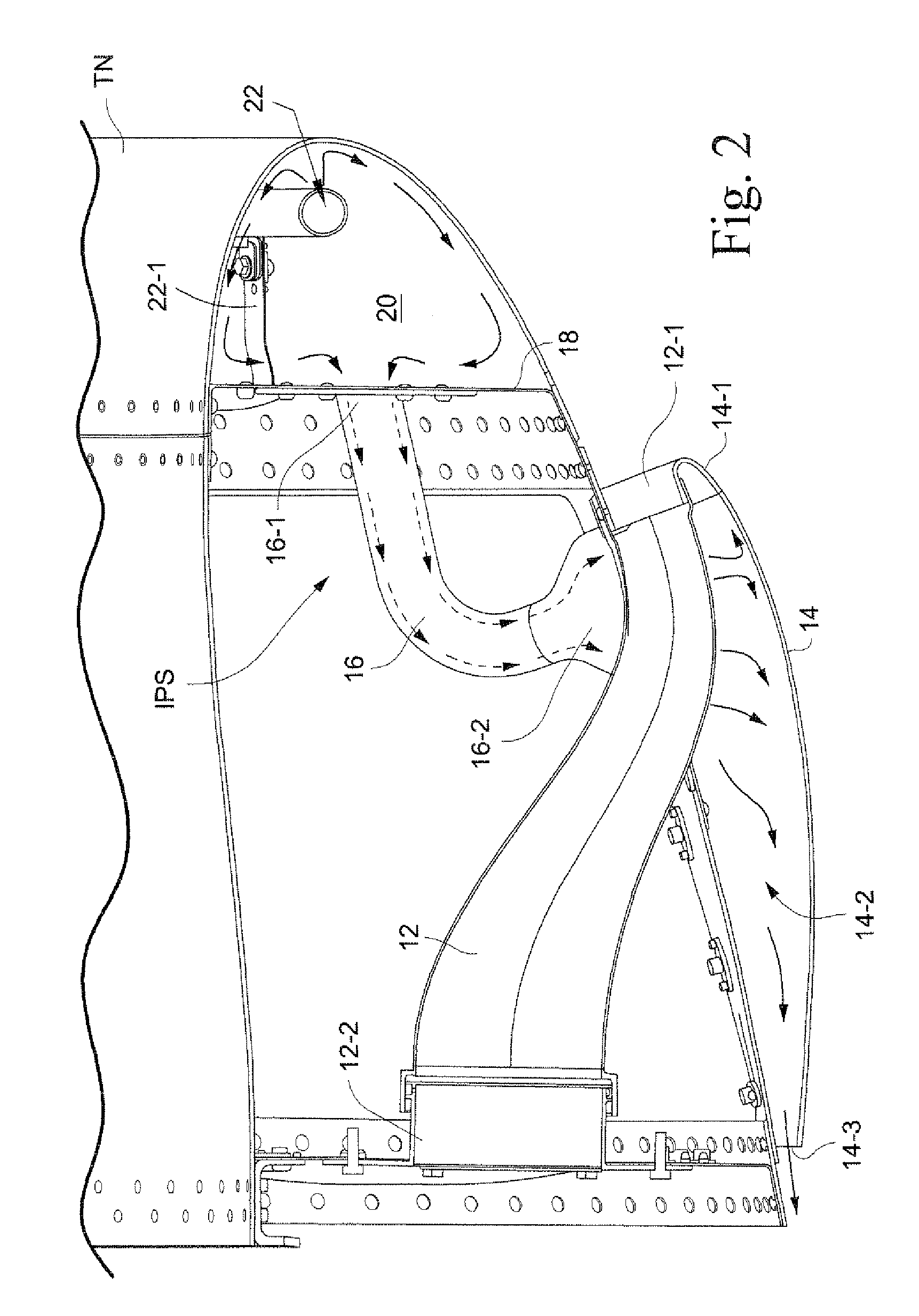
[0017]As is perhaps best shown in FIG. 2, the air scoop 10 includes a ram air duct 12 having a forward air inlet opening 12-1 and a rear air discharge opening 12-2. A fairing 14 covers at least a forward end portion of the air duct 12 and includes a forward end 14-1 which surrounds the air inlet opening 12-1. The fairing 14 defines a space 14-2 which terminates in a rearward discharge opening 14-3.

[0018]As shown in FIG. 3, the air scoop icing protection system IPS includes a pair of tubes 16 each having an inlet end 16-1 which penetrates through a bulkhead plate 18 provided in the nacelle ...


PUM


Abstract

Aircraft air scoop icing protection systems and methods include an air duct having air inlet and outlet openings and a fairing which covers the air duct and defines an interior fairing space in which at least a forward portion of the air duct is positioned. The fairing has a forward end which surrounds the air inlet of the air duct. At least one tube is provided having an inlet end in communication with a heated air chamber associated with an airframe structure of the aircraft, and an outlet end in communication with the interior fairing space. Heated air in the heated chamber is directed through the tube to the interior fairing space so as to provide icing protection to the air duct. The air scoop icing protection systems may advantageously be employed so as to provide icing protection to air scoops associated with an aircraft engine nacelle using the residual heat from the nacelle's inlet lip primary bleed air system.

Description

FIELD OF THE INVENTION[0001]The devices and methods disclosed herein relate generally to aircraft icing protection techniques. In preferred forms, the disclosed devices and methods provide icing protection for aircraft air inlet scoops utilizing residual thermal energy from heated air discharged from an aircraft's primary bleed air icing protection system.BACKGROUND AND SUMMARY OF THE INVENTION[0002]Aircraft in flight sometimes encounter icing conditions whereby ice accretes onto airframe components. If left unchallenged, ice accretion on airframe components severely degrades aircraft performance, for example, by degrading the aerodymanic characteristics of lift surfaces, disruption of engine air flow and blockage of cooling air inlets and the like. Therefore, aircraft certified for flight into known icing conditions will have its flight critical airframe components equipped with icing protection systems.[0003]A variety of icing protection systems are known. For example, airframe co...

Claims


Application Information

Patent Timeline
Patent Type & Authority Applications(United States)
IPC IPC(8): B64D15/04B64D27/00
CPCB64D15/04B64D2033/0286B64D2033/0233B64D33/10
Inventor DE SOUZA, FRANCISCO JOSETRAPP, LUIS GUSTAVO
Owner EMBRAER SA
Learn More