
Microcomponent Provided with a Cavity Delimited by a Cap with Enhanced Mechanical Resistance

a technology of mechanical resistance and micro-components, which is applied in the direction of micro-structural devices, electrical devices, special surfaces, etc., can solve the problems of affecting the progression or even damage of the component, the additional space occupied by the presence of the pillars is a non-negligible drawback, and the deformation of the component may be significant under pressur

Active Publication Date: 2009-08-06
COMMISSARIAT A LENERGIE ATOMIQUE ET AUX ENERGIES ALTERNATIVES
View PDF2 Cites 41 Cited by
  • Summary
  • Abstract
  • Description
  • Claims
  • Application Information

AI Technical Summary

Benefits of technology

[0012]The aim of the invention is specifically to propose a microcomponent provided wlth a cavity delimited by a cap wherein the mechanical resistance is enhanced and which does not involve the drawbacks mentioned above and particularly does not involve the stress generated by the pillars inside the cavity and which is easy to manufacture using conventional thin layer deposition techniques.

Problems solved by technology

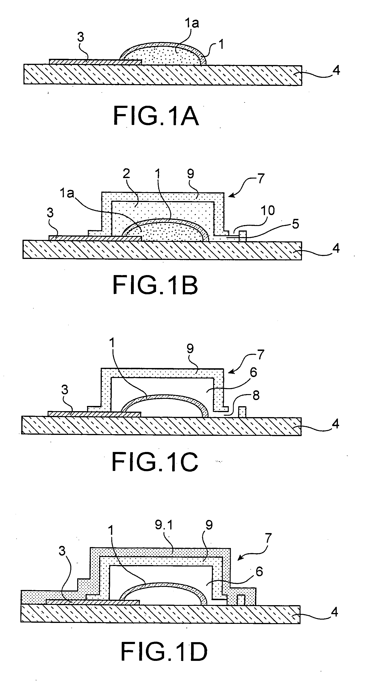
If the deflection of the cap 7 is excessive, it may come into contact with the active part 1, affect its progression or even damage it.
The deformation thereof under the effect of pressure may be significant.
However, rigid materials which are suitable for their mechanical properties are not necessarily commonly used in microelectronics and in microsystems and the introduction thereof may be difficult to implement, they may pose contamination problems or require specific developments.
The additional space occupied due to the presence of the pillars is a non-negligible drawback.
In addition, Ate design of the microsystem is limited as it is necessary to account for the position of the pillars.
Moreover, in some cases, It is not possible to anchor the pillars on the substrate which forms the base of the cavity.

Method used


Image

  • Microcomponent Provided with a Cavity Delimited by a Cap with Enhanced Mechanical Resistance
  • Microcomponent Provided with a Cavity Delimited by a Cap with Enhanced Mechanical Resistance
  • Microcomponent Provided with a Cavity Delimited by a Cap with Enhanced Mechanical Resistance

Examples


Embodiment Construction

[0012]The aim of the invention is specifically to propose a microcomponent provided wlth a cavity delimited by a cap wherein the mechanical resistance is enhanced and which does not involve the drawbacks mentioned above and particularly does not involve the stress generated by the pillars inside the cavity and which is easy to manufacture using conventional thin layer deposition techniques.

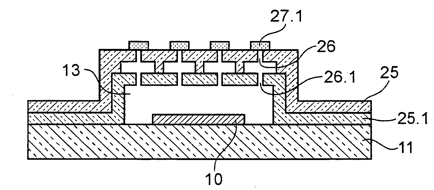
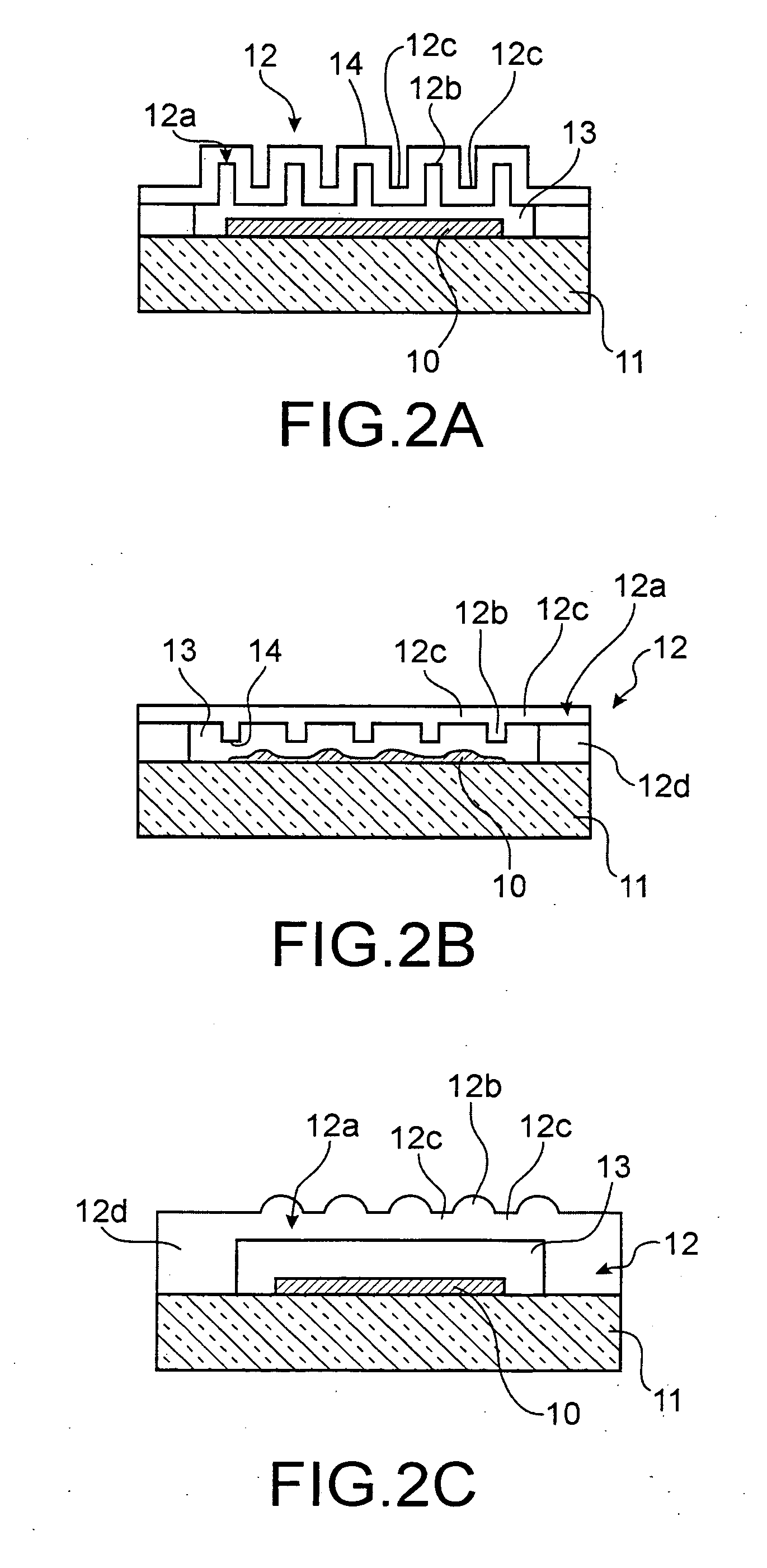
[0013]In order to achieve these aims, the invention relates more specifically to a microcomponent comprising a cavity delimited by a cap enclosing an active part supported by a substrate. The cap comprises a top wall comprising stiffening means with at least one projecting stiffening member, said projecting stiffening member being located between two recessed areas of the top wall and having one end at a distance from the recessed areas without coming into contact with the substrate.

[0014]The projecting stiffening member may advantageously take the form of a moulding or a block.

[0015]The moulding ...


PUM

PropertyMeasurementUnit
pressuresaaaaaaaaaa
thicknessaaaaaaaaaa
thicknessaaaaaaaaaa

Abstract

It consists of a microcomponent comprising a cavity (13) delimited by a cap (12) enclosing an active part (10) supported by a substrate (11) The cap (13) comprises a top wall (12a) comprising stiffening means with at least one projecting stiffening member (12b) said stiffening member (12b) being located between two recessed areas (12c) of the top wall (12a) and having one end (14) at a distance from the recessed areas (12c) without coming into contact with the substrate (11).

Description

FIELD OF THE INVENTION[0001]The present invention relates to a microcomponent provided with a cavity delimited by a cap with enhanced mechanical resistance.[0002]The packaging of microelectromechanical systems known as MEMS is now a key to their development. Other electronic, optical or optoelectronic microcomponents may also be concerned by this packaging. Hereinafter, the term microcomponent has been used which in this case covers a microsystem, an electronic, optical or optoelectronic component.[0003]The cavity is generally rendered hermetic to gas and moisture so as to limit their ageing. Dust is also prevented from disturbing their operation, particularly in the case of mobile parts. It may also be required to control the atmosphere inside the cavity for example by introducing a neutral gas therein which will prevent any chemical reaction with the microcomponent or by producing a vacuum. In fact, the oxygen in the ambient air may degrade the contacts thereof. The cap also makes...

Claims


Application Information

Patent Timeline
Patent Type & Authority Applications(United States)
IPC IPC(8): H05K5/00B05D5/12B81C99/00
CPCB81B3/007B81C2203/0163B81C2203/0145B81C2203/0136
Inventor GILLOT, CHARLOTTEPORNIN, JEAN-LOUISLAGOUTTE, EMMANUELLEJACQUET, FABRICEHENTZ, SEBASTIEN
Owner COMMISSARIAT A LENERGIE ATOMIQUE ET AUX ENERGIES ALTERNATIVES
Learn More