
Holder Devices for Annuloplasty Devices Having a Plurality of Anterior-Posterior Ratios

a technology of annuloplasty and holder device, which is applied in the field of holder device for holding annuloplasty device having a plurality of anterior-posterior ratios, can solve the problems of dilation, distortion of the normal shape of the valve orifice, and/or distortion of the base of the aortic valve, and achieves the effects of improving the repair efficiency and reducing the risk of complications

Active Publication Date: 2009-07-30
MEDTRONIC INC
View PDF99 Cites 152 Cited by
  • Summary
  • Abstract
  • Description
  • Claims
  • Application Information

AI Technical Summary

Benefits of technology

[0015]Embodiments of the present invention offer advantages. The holder device of the present invention provides one holder device that is able to hold annuloplasty devices having different A-P ratios, but corresponding to the same size of valve annulus. Thus, an advantage of the present invention is that only one holder device needs to be made to accommodate a plurality of different annuloplasty devices. This reduces the cost and time associated with tooling holder devices for each separate annuloplasty device of a given inter-trigonal (or inter-commissural) distance and A-P ratio.
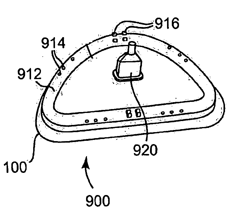
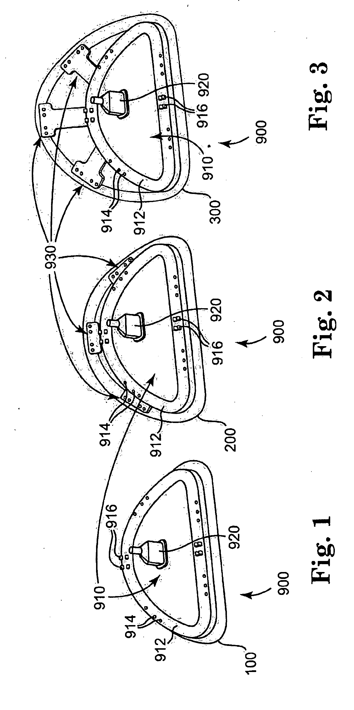
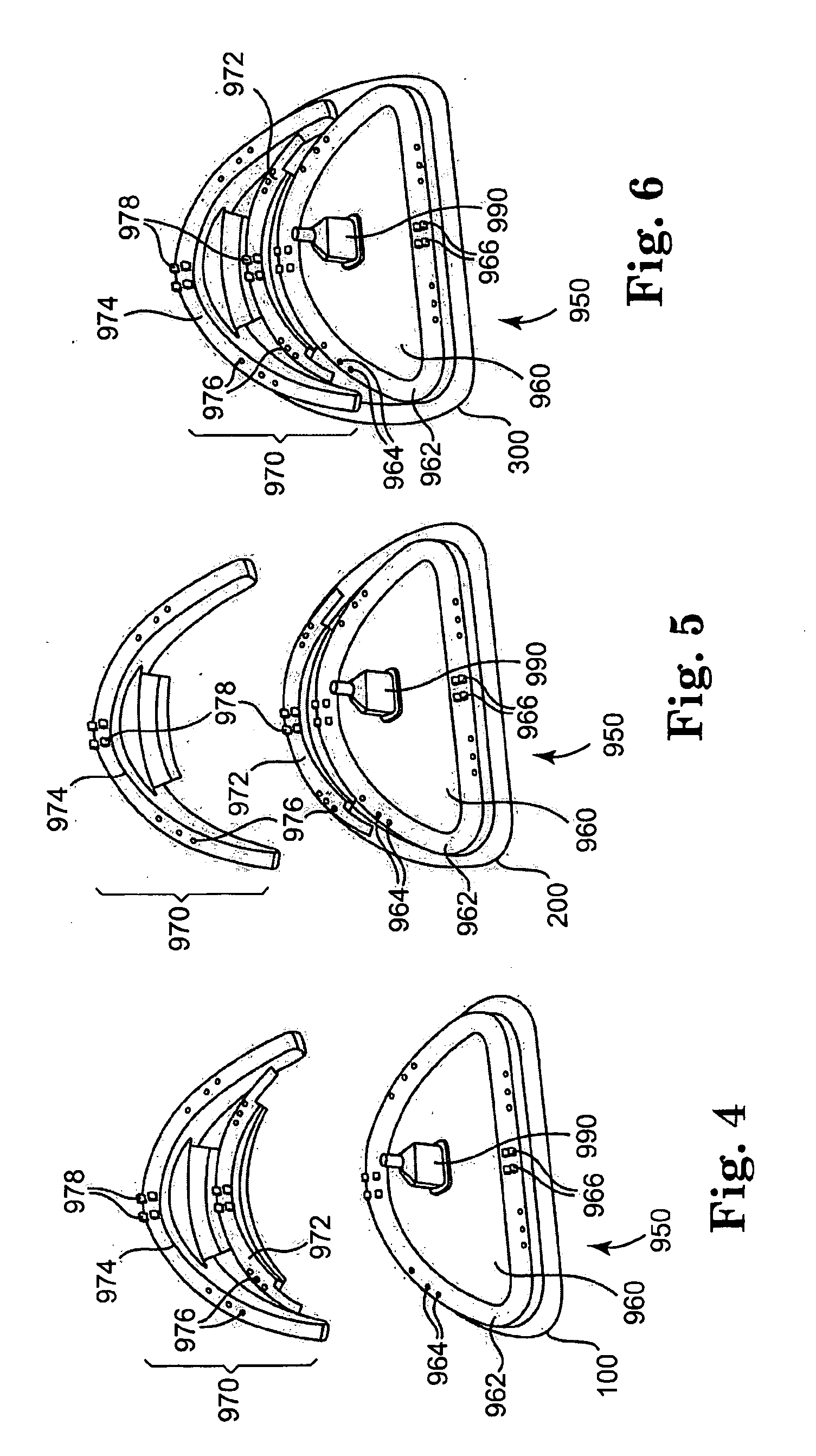
[0016]One aspect of the present invention is an adjustable annuloplasty device holder possible of having a plurality of different anterior-posterior ratios. The holder may comprise a member having an anterior segment and a posterior segment that are shaped to hold an anterior portion and a posterior portion, respectively, of an annuloplasty device, wherein the anterior segment has a given size and the posterior segment is adjustable in order to change the anterior-posterior ratio of the holder to accommodate annuloplasty devices having a plurality of different anterior-posterior ratios. The holder may further comprise a plurality of radially extending flanges in the posterior segment that are extendible varying distances in order to change the anterior-posterior ratio of the holder. The holder may also further comprise at least one detachable flange that may be attached to or detached from the member in order to change the anterior-posterior ratio of the holder. The member may have an outer circumferential surface to which at least the anterior portion of the annuloplasty device is mounted and the plurality of radially extending flanges may be slidably disposed within the member. The posterior portion of the annuloplasty device may be mounted to the plurality of flanges. The at least one detachable flange may be attached to the member by a snap-fit connection. The holder may comprise first and second detachable flanges, and the first detachable flange may be attached to the member and the second detachable flange may be attached to the first detachable flange. The first and second detachable flanges may be attached to the member and each other using snap-fit connections. The given size of the anterior segment may correspond to an inter-trigonal or inter-commissural distance of a heart valve annulus.
[0017]A second aspect of the present invention is a method of using an adjustable annuloplasty holder device. The method may comprise the steps of: receiving an adjustable annuloplasty device holder possible of having a plurality of different anterior-posterior ratios, the holder comprising a member having an anterior segment and a posterior segment that are shaped to hold an anterior portion and a posterior portion, respectively, of an annuloplasty device, wherein the anterior segment has a given size and the posterior segment is adjustable in order to change the anterior-posterior ratio of the holder to accommodate annuloplasty devices having a plurality of different anterior-posterior ratios; receiving an annuloplasty device of the given size of the anterior segment of the holder and of a given anterior-posterior ratio; adjusting the posterior segment of the holder such that the member has the given anterior-posterior ratio of the annuloplasty device; and mounting the annuloplasty device to the holder. The method may further comprise the steps of: delivering the annuloplasty device mounted on the holder to a heart valve annulus; suturing the annuloplasty device to the heart valve annulus; removing the annuloplasty device from the holder; and withdrawing the holder. The adjustable annuloplasty device holder may further comprise a plurality of radially extending flanges in the posterior segment that are extendible varying distances in order to change the anterior-posterior ratio of the holder, and the adjusting step may comprise extending the flanges to provide the given anterior-posterior ratio. The plurality of radially extending flanges may be slidably disposed within the member. The mounting step may comprise mounting the annuloplasty device to the plurality of flanges. The adjustable annuloplasty device holder may further comprise at least one detachable flange that may be attached to or detached from the member in order to change the anterior-posterior ratio of the holder, and the adjusting step may comprise attaching or detaching the at least one flange. The at least one detachable flange may be attached to the member by a snap-fit connection. The holder may comprise first and second detachable flanges, and the first detachable flange may be attached to the member and the second detachable flange may be attached to the first detachable flange. The first and second detachable flanges may be attached to the member and each other using snap-fit connections.

Problems solved by technology

In either area of the heart, however, many of the defects are associated with dilation of the valve annulus.
This dilation not only prevents competence of the valve but also results in distortion of the normal shape of the valve orifice.
A significant surgical diminution of the inter-trigonal distance may cause left ventricular outflow obstruction and / or distortion of the base of the aortic valve.

Method used


Image

  • Holder Devices for Annuloplasty Devices Having a Plurality of Anterior-Posterior Ratios
  • Holder Devices for Annuloplasty Devices Having a Plurality of Anterior-Posterior Ratios
  • Holder Devices for Annuloplasty Devices Having a Plurality of Anterior-Posterior Ratios

Examples


Embodiment Construction

[0021]With reference to the accompanying figures, wherein like components are labeled with like numerals throughout the several figures, an annuloplasty device holder is disclosed, taught and suggested.

[0022]In particular, the holder device of the present invention will correspond to one of a plurality of possible sizes of annulus, i.e., inter-trigonal or inter-commissural distances. The holder device will also be capable of holding annuloplasty devices that have different A-P ratios. A purpose of the holder device being able to hold annuloplasty device having varying A-P ratios is to reduce the number of holder devices that are necessary for a given set of annuloplasty devices.

[0023]Heart valve annuli having the same inter-trigonal (or inter-commissural) distance may have different A-P ratios due to different disease states of the valves, for example. Thus, a surgeon may measure the inter-trigonal distance (or inter-commissural distance) and may still have to choose between a plura...


PUM


Abstract

Described is an adjustable annuloplasty device holder possible of having a plurality of different anterior-posterior ratios, the holder comprising a member having an anterior segment and a posterior segment that are shaped to hold an anterior portion and a posterior portion, respectively, of an annuloplasty device, wherein the anterior segment has a given size and the posterior segment is adjustable in order to change the anterior-posterior ratio of the holder to accommodate annuloplasty devices having a plurality of different anterior-posterior ratios. Also described is a method of using such an adjustable annuloplasty holder device.

Description

PRIORITY [0001]The present non-provisional patent application claims benefit from U.S. Provisional Patent Application having Ser. No. 61 / 062,412, filed on Jan. 25, 2008, by Ryan et al., and titled SYSTEM OF ANNULOPLASTY DEVICES WITH VARYING ANTERIOR-POSTERIOR RATIOS AND RELATED DEVICES AND METHODS, wherein the entirety of said provisional patent application is incorporated herein by reference.TECHNICAL FIELD [0002]The present invention relates generally to devices and methods for repair of heart valves, and more particularly to a holder devices for holding annuloplasty devices having varying anterior-posterior ratios to treat different pathologies.BACKGROUND OF THE INVENTION [0003]Heart valve disease is a widespread condition in which one or more of the valves of the heart fails to function properly. Various surgical techniques may be used to replace or repair a diseased or damaged valve. In just one way, in a valve replacement surgery, damaged leaflets of the valve are excised and ...

Claims


Application Information

Patent Timeline
IPC IPC(8): A61F2/24
CPCA61B5/1076A61F2/2496A61F2/2448
Inventor GLOSS, MICHAEL A.KUEHN, STEPHEN
Owner MEDTRONIC INC
Learn More