Cooking device

a technology of cooking device and electric wire, which is applied in the direction of electrical/magnetic/electromagnetic heating, microwave heating, electrical apparatus, etc., can solve the problems of bending of electric wire, insufficient consideration of durability and professional use, and difficulty in providing electric wire in a portion, so as to reduce the bend of electric wir

Inactive Publication Date: 2009-07-30
SHARP KK
View PDF5 Cites 6 Cited by
  • Summary
  • Abstract
  • Description
  • Claims
  • Application Information

AI Technical Summary

Benefits of technology

[0042]Therefore, it is possible to reduce the bend of the electric wires caused because the electric wires are distorted along the central axes shifted from each other within the hinge shaft and the guide section in opening / closing the door.

Problems solved by technology

In the cooking device disclosed in Japanese Laid-Open Patent Publication No. 2000-12209 or 2002-48346, however, in the case where the door is highly frequently opened / closed over a long period of time, it is apprehended that the electric wire may be disconnected due to repeated bend or torsion.
Therefore, durability also for the professional use is not sufficiently considered in the techniques disclosed in these publications.
On the contrary, when the door opens laterally, it is very difficult to provide the electric wire in a portion minimally seen by a user and not disturbing the opening / closing of the door merely because hinges are provided on left end portions of the front side and the control circuit of the cooking device body is provided on the right hand side.

Method used


Image

  • Cooking device
  • Cooking device
  • Cooking device

Examples


Embodiment Construction

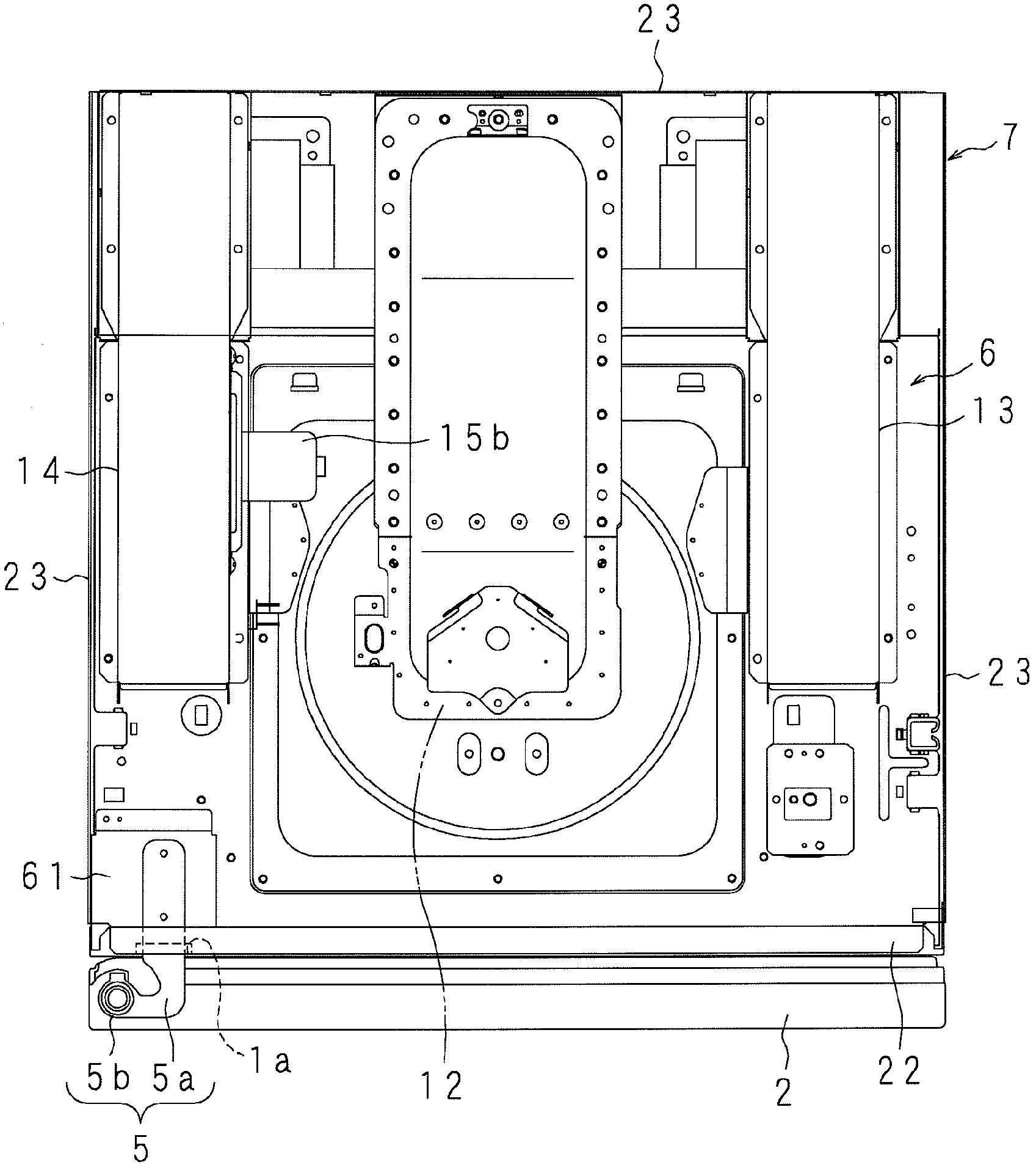
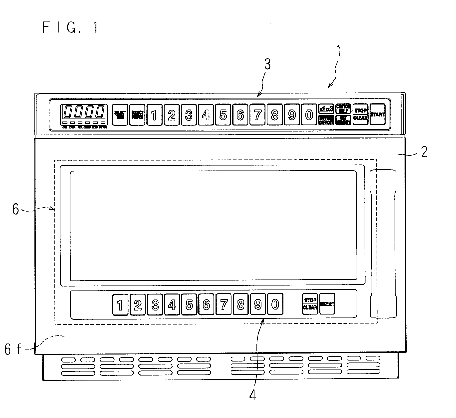
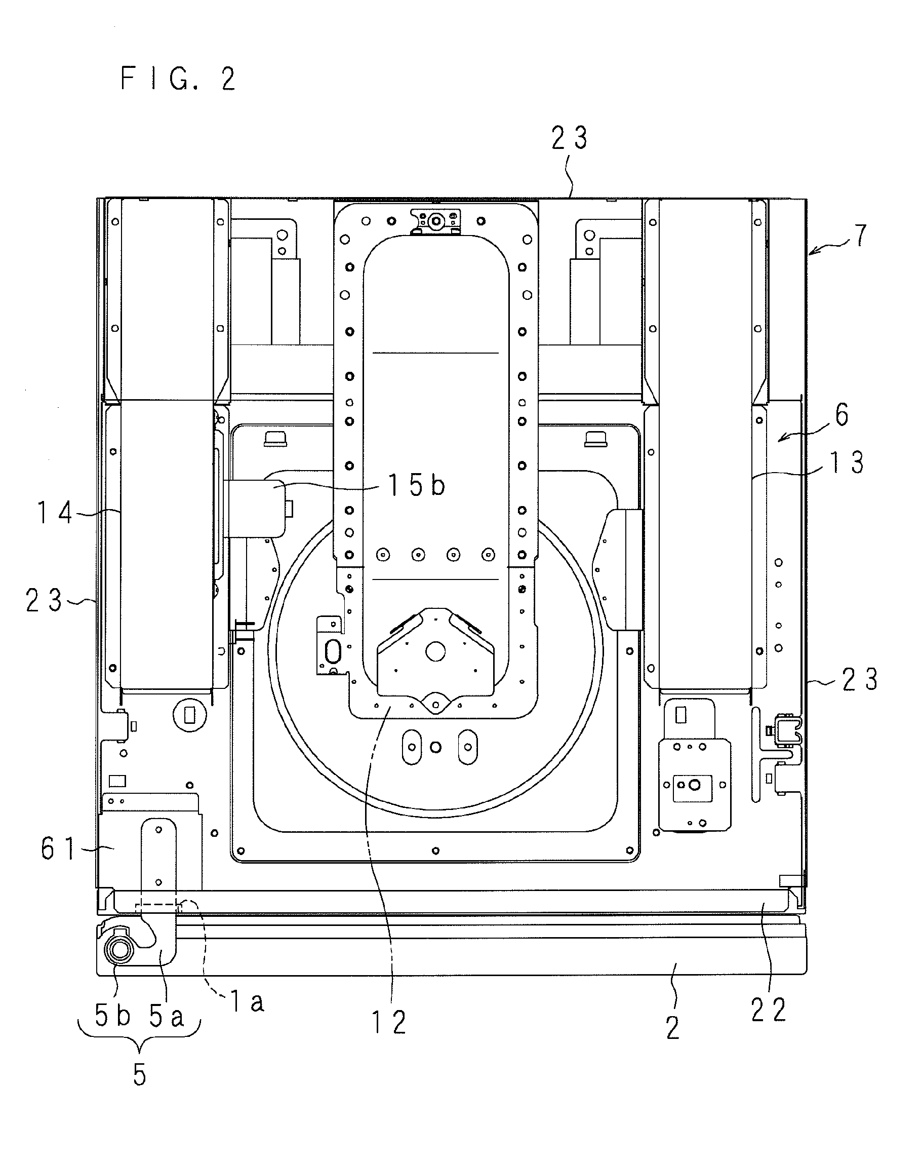
[0054]Now, an embodiment in which the cooking device of this invention is applied to a microwave oven will be described in detail. FIG. 1 is a front view showing the external appearance of the microwave oven, and FIGS. 2 through 5 are respectively schematic plan, rear, left side and right side views showing the internal structure of the microwave oven.

[0055]In these drawings, a reference numeral 1 denotes an oven body. The oven body 1 is in a substantially rectangular parallelepiped shape and includes, as an outer hull, a cabinet 7 containing a heating chamber 6 having an open section on the front side. The open section is closed in an openable manner by a laterally opening door 2 hinged on one side of a front portion of the oven body 1. An upper portion of the front face of the oven body 1 protrudes forward so as to cover a top portion of the door 2, and operation sections 3 and 4 used for accepting operations such as selection of recipes and start of heating are respectively provi...


PUM


Abstract

Multicore electric wires 31 for connecting an operation key sheet 4a and a control section of an oven body are loosely inserted into a hinge shaft 5b in a cylindrical shape and a door pipe 30 in a cylindrical shape having a length exceeding a half of the height of a door 2, and the door pipe 30 guides the electric wires 31 along the axial direction of the hinge shaft 5b. When the door 2 is opened/closed, torsional stress caused in the electric wires 31 are dispersed over the electric wires 31 disposed correspondingly to the length of the door pipe 30.

Description

CROSS-REFERENCE TO RELATED APPLICATION[0001]This non-provisional application claims priority under 35 U.S.C. §119(a) on Patent Application No. 2008-019807 filed in Japan on Jan. 30, 2008, the entire contents of which are hereby incorporated by reference.BACKGROUND[0002]1. Technical Field[0003]The present invention relates to a cooking device using a heat source of microwave, electric heaters or the like for heating / cooking an object placed in a heating chamber.[0004]2. Description of Related Art[0005]Recently, cooking devices using microwave and / or electric heaters as a heat source have been widely spread. Cooking devices particularly for professional use are required to perform a comparatively simple operation rapidly, and a plurality of such devices are sometimes stacked for use in order to effectively utilize a limited space for installing them.[0006]In a cooking device, user-friendliness largely depends upon the arrangement of an operation section and operation switches, and hen...

Claims


Application Information

Patent Timeline
Patent Type & Authority Applications(United States)
IPC IPC(8): H05B6/80
CPCH05B6/6414
Inventor KIMURA, KENJIHIRANO, SEIICHI
Owner SHARP KK
Why Eureka
Try Eureka