Panelization System and Method

a panelization system and panel technology, applied in the field of panelization systems, to achieve the effects of reducing the field of vision, increasing the speed, and limiting the flexibility of architectural and aesthetics

Active Publication Date: 2009-07-30
NEW MILLENNIUM BUILDING SYST +1
View PDF52 Cites 8 Cited by
  • Summary
  • Abstract
  • Description
  • Claims
  • Application Information

AI Technical Summary

Benefits of technology

[0013]The present invention, however, provides a method for assembling a complete, panel system (without the layer of concrete) on the ground, and then lifting the preassembled panel onto temporary support elements fixed to the columns at the desired building elevations. For example, the panelization system of the present invention encompasses placing preassembled floor or roof panels of various sizes directly into place “at height” in the building. Because these panels incorporate beams that run along the sides of columns and not directly between and along the centerline of the columns, the panels can be set in place on temporary support elements before being permanently attached to the columns. This alleviates the need to place, suspend, or otherwise secure the construction components in their exact final position before permanently attaching them. In short, the maneuvering and installation of individual floor or roof panels and frame components “at height” is completely avoided.
[0014]The fact that the horizontal frame of the present invention is supported on temporary support elements on the sides of columns also increases the speed with which a multi-story building can be constructed. For example, in traditional piece by piece construction, a crane is required to hold a particular component in position while it is being attached to the building's vertical and / or horizontal frame. With the present invention, the floor or roof panel is simply rested on temporary support elements and left in place by the crane operator. The crane is then free to begin raising a second panel while the first is being permanently attached to the columns.
[0015]There are also several aspects of the present invention that allow for a safer worksite. First, the panelization system of the present invention allows for more work to be conducted at ground level as opposed to “at height.” Naturally, all other factors being equal, it is safer to conduct work on the ground than it is to conduct work elevated well above the ground. Moreover, floor or roof panels can be outfitted with safety railings on the ground to thereby provide immediate fall protection once the floor or roof panel is lifted into place. Finally, the use of temporary support elements for the panels provides a place for workers to stand while a panel is placed on the opposing side of a column. This would not be possible if the frame component was attached to the top or along the centerline of the column instead of to the side of the column as in the present invention.
[0016]Another feature of the present invention in a floor or roof application is the use of a spandrel beam system that can match the overall depth of the floor or roof component. In building construction, the beam that extends from column to column at the boundary or exterior edge and marks the floor or roof level between stories is commonly referred to as a spandrel beam. Spandrel beams are designed to support the vertical and lateral loads imposed by the exterior fascia of the building, also referred to as the curtain wall. Spandrel beams can also support floor or roof gravity weight loads. Traditionally, the challenge has been providing reinforcement to the spandrel beam without increasing the thickness of the floor or roof component, and thereby avoiding the need for a deeper beam section at the exterior. These deeper beam sections form a bulkhead that reduces the field of vision and limits architectural and aesthetic flexibility. The top and bottom of the spandrel beam system of the present invention can be flush with the top and bottom of the floor or roof component of a building. Accordingly, the spandrel beam system accomplishes the challenging task of supporting a curtain wall, while still providing an uninterrupted ceiling, without a bulkhead adjacent to the curtain wall. The spandrel beam system of the present invention can also be used as a drag strut which is an integral part of a building's lateral support system.
[0017]Another feature of the present invention is the ability to place MEP items and other building components on the panel when the panel is on the ground, thus further minimizing work done “at height.”
[0018]Another feature of the present invention is the ability to temporarily store various construction materials and equipment on the panel prior to the panel being raised and installed. Once the panel is installed, the temporarily stored materials can be offloaded or otherwise distributed. Furthermore, the installed panel comprises a safe platform upon which workers can immediately begin working. All of these features contribute to a safer and more efficient construction site.

Problems solved by technology

Striking a balance among these often-competing concerns is the challenge faced in developing panelization systems.

Method used


Image

  • Panelization System and Method
  • Panelization System and Method
  • Panelization System and Method

Examples


Embodiment Construction

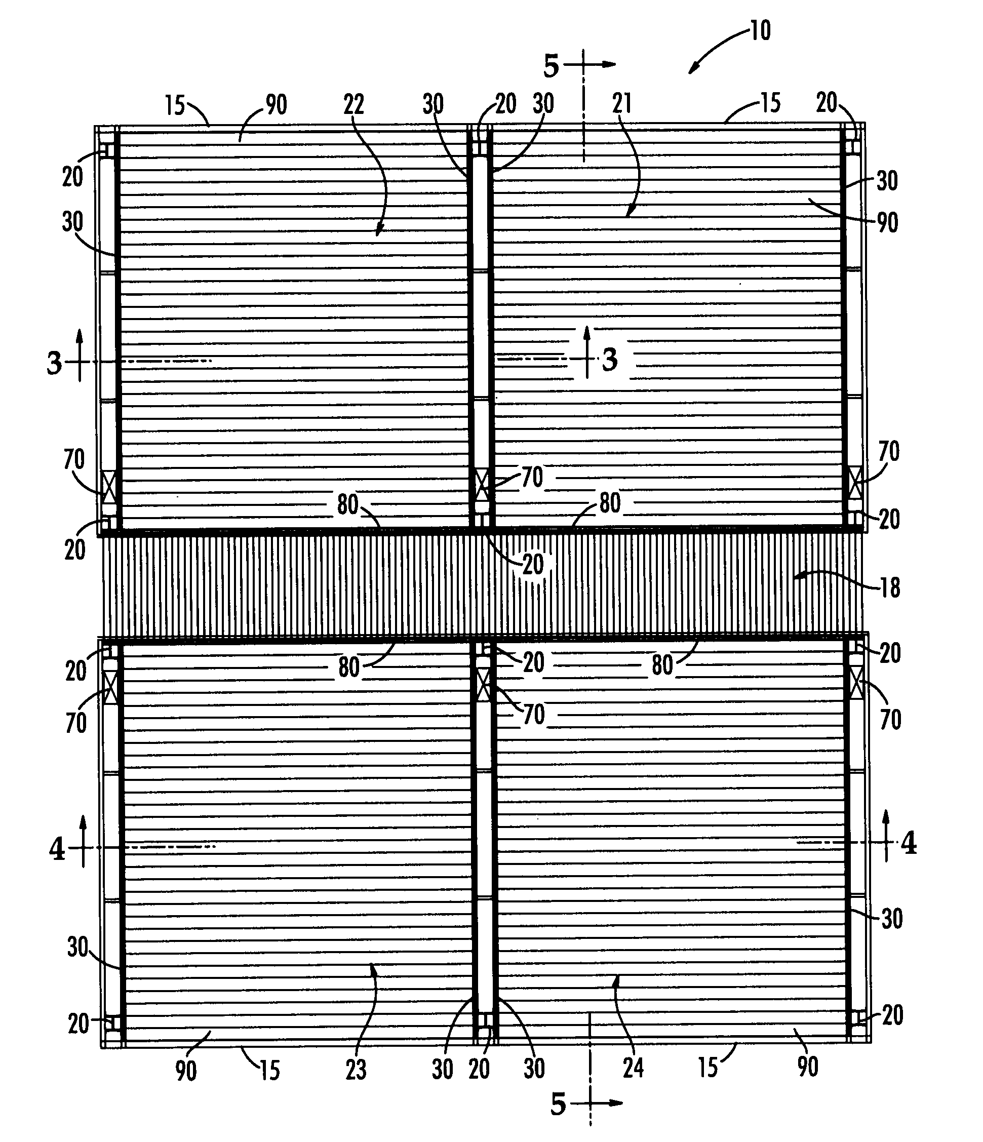
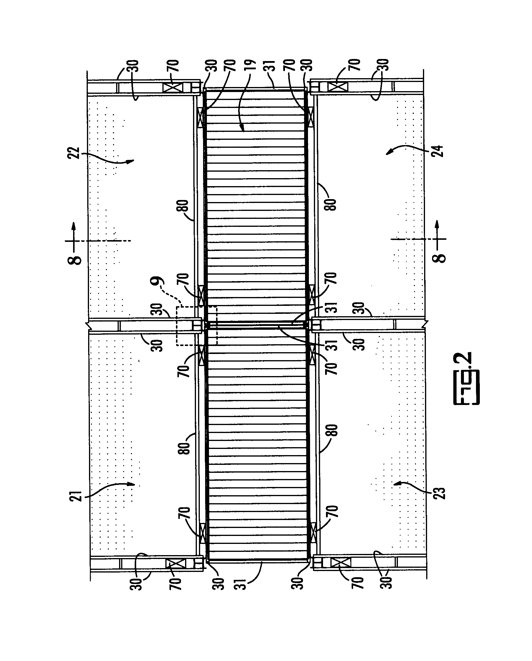
[0039]The present invention is a panelization system and method. As illustrated in the drawings and in particular the embodiment in FIG. 1, the panelization system 10 is comprised of exterior preassembled panels 21, 22, 23, and 24, and a field installed interior partition 18. Each of the exterior floor or roof panels 21, 22, 23, and 24 includes a floor component, such as deck 90, and a frame 30. The panelization system 10 of the present invention is ideal for use in a variety of construction projects, not just for flooring, and is easily interfaced with a variety of conventional construction components. By way of example and not limitation, the panelization system 10 of the present invention is shown as being incorporated into a building having a plurality of columns 20 that form the perimeters of the four floor panels 21, 22, 23, and 24.

[0040]As further illustrated in FIG. 1, adjacent pairs of exterior panels (i.e. 21, 22 and 23, 24) are attached to both sides of columns 20 with co...


PUM


Abstract

A prefabricated panelization system having a floor or roof component and a frame component. In particular, the floor or roof component includes a deck member, which can be made of deck sections, profiles, or panels. For example, the deck member can be made of continuous panels that cover the desired width and length of the floor or roof component without intermediate beams between supporting elements. Alternatively, the deck members can be made of individual or panelized sections that are combined in juxtaposed relation to form the desired width and length. The frame component includes opposing horizontal support channels that are attached to opposing columns, respectfully.

Description

CROSS REFERENCE TO RELATED APPLICATIONS:[0001]This continuation-in-part application claims priority to the non-provisional application bearing Ser. No. 12 / 019,138 filed Jan. 25, 2008.STATEMENT REGARDING FEDERALLY SPONSORED RESEARCH OR DEVELOPMENT [0002]Not applicable.REFERENCE TO A SEQUENCE LISTING, A TABLE, OR A COMPUTER PROGRAM LISTING COMPACT DISC APPENDIX [0003]Not Applicable.BACKGROUND OF THE INVENTION [0004]The present invention relates generally to panelization systems and, more particularly, to systems employing prefabricated frames and deck pans for constructing floors, roofs, or platforms of buildings or other structures.[0005]Some concerns in building construction and design are minimizing costs, maintaining a safe working environment, and maximizing architectural flexibility and creativity. Striking a balance among these often-competing concerns is the challenge faced in developing panelization systems. The present invention incorporates unique construction methods that ...

Claims


Application Information

Patent Timeline
Patent Type & Authority Applications(United States)
IPC IPC(8): E04B5/17E04G21/14
CPCE04B5/40E04B5/10E04B5/43
Inventor WILLIAMS, MARTIN R.JACOBSON, C. ERICLINDLEY, II, BILL R.
Owner NEW MILLENNIUM BUILDING SYST
Why Eureka
Try Eureka