
Rapid Chilling Device for Vitrification

a technology of vitrification and chilling device, which is applied in the direction of mechanical apparatus, biomass after-treatment, container discharge method, etc., can solve the problems of exposing biological specimens to contamination, slow chilling speed requires high, and often toxic vitrification media, etc., to reduce the leidenfrost effect in vitrification and high cryogen velocity

Inactive Publication Date: 2009-07-23
COOK MEDICAL TECH LLC
View PDF44 Cites 21 Cited by
  • Summary
  • Abstract
  • Description
  • Claims
  • Application Information

AI Technical Summary

Benefits of technology

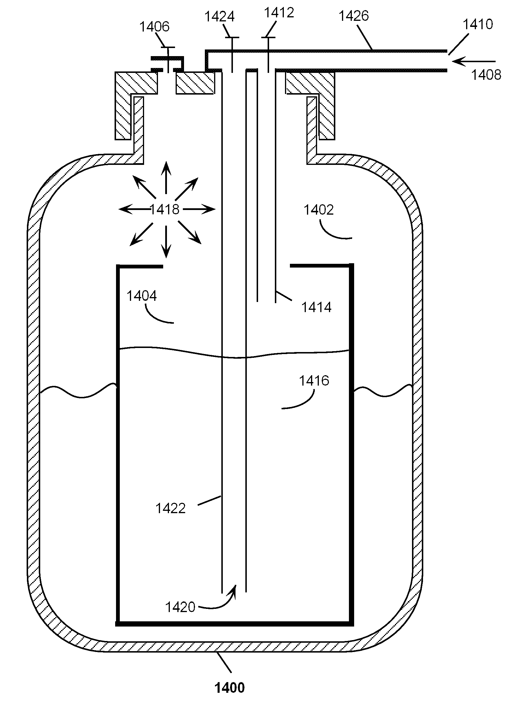
[0014]In one embodiment of this invention, a saturated cryogen is held in a closed dewar whose exterior is exposed to room temperature. Ambient warming pressurizes the dewar and this pressure forces the saturated cryogen out of the dewar as a fluid jet. This jet is directed onto the vitrification device and forcefully displaces the evolved vapors to prevent formation of the Leidenfrost effect.

Problems solved by technology

Vitrification media, however, are often toxic to cells when the cells are warm.
Slow chilling speeds require high, relatively toxic concentrations of vitrification media, such as 60% w / w CPA concentration.
Directly plunging a biological specimen into LN2 achieves rapid chilling, but may expose biological specimens to contamination.
One of the limitations to achieving the fastest possible chilling speed with either direct plunge open cryocontainers or closed cryocontainers is that contact of the initially warm vitrification device with LN2 will result in the generation of an insulating nitrogen vapor coating around said device.

Method used


Image

  • Rapid Chilling Device for Vitrification
  • Rapid Chilling Device for Vitrification
  • Rapid Chilling Device for Vitrification

Examples


Embodiment Construction

[0030]The following detailed description discloses various embodiments and features of the invention. These embodiments and features are meant to be exemplary and not limiting.

[0031]As used herein, except for temperature and unless specifically indicated otherwise, the term “about” means within + / −20% of a given value for a parameter. For temperature, “about” means + / −2° C. of a given value.

[0032]A variety of biological cells can be aseptically cryopreserved (vitrified) using the present invention. One category of cells is mammalian developmental cells such as sperm, oocytes, embryos, morulae, blastocysts, and other early embryonic cells. These cells may be cryopreserved during assisted reproduction procedures. Another category is stem cells that are used in regenerative therapies. The broadest category is any cell or group of cells that can be vitrified with the available chilling speeds of this invention.

Vitrification Devices

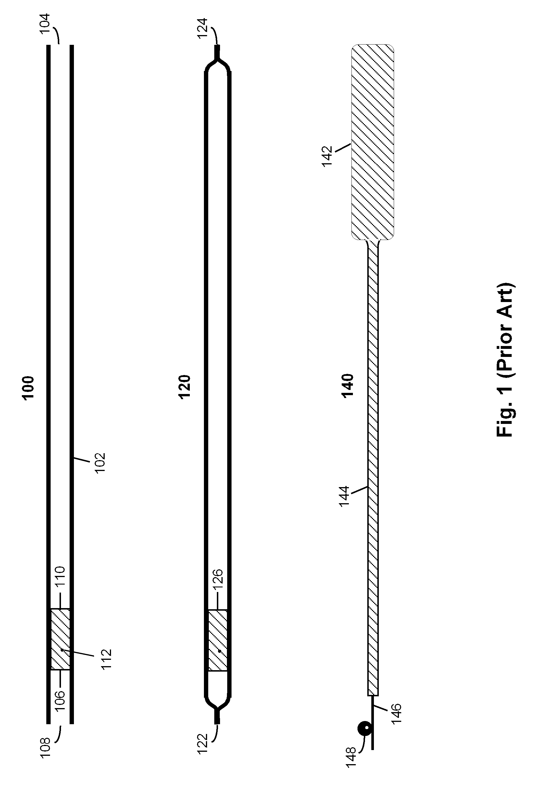
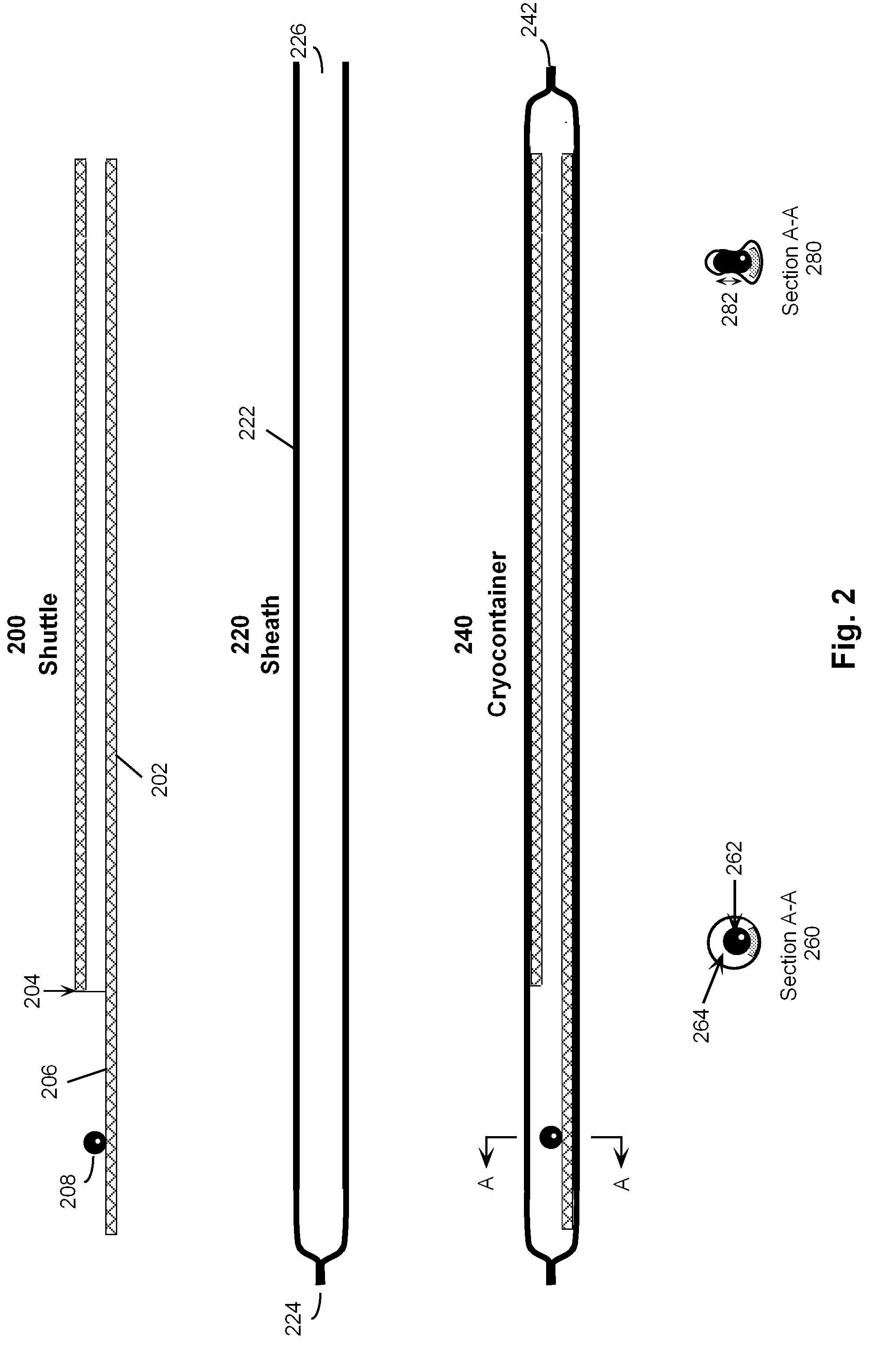
[0033]Cryocontainers used as vitrification devices span ...


PUM


Abstract

Successful cryopreservation by the vitrification method depends on high chilling speed. Practitioners of vitrification prefer to use liquid nitrogen as the chilling cryogen due to its inherent safety and low cost. Plunging vitrification cryocontainers in to a quiescent pool of liquid nitrogen invariably results in a chilling rate less than the theoretical potential. The shortfall is attributed to the well-known Leidenfrost effect. The purpose of this invention it to provide improve chilling rates during vitrification using liquid nitrogen. One feature of this invention is a contacting device that invokes convective heat transfer principles to increase chilling speed. In another feature of this invention, cryogen velocity is derived from a self-pressurized dewar containing a saturated cryogen. The self-pressurization is achieved by ambient heating of the dewar's contents. In another embodiment, a sub-cooled cryogen, such as propane, is used in tandem with a saturated cryogen, such as LN2, in a self-pressurized dewar.

Description

CROSS-REFERENCE TO RELATED APPLICATIONS[0001]This application claims priority to U.S. provisional patent application entitled “Rapid Chilling Device for Vitrification”, Ser. No. 61 / 021,661 filed on Jan. 17, 2008. Said provisional application is incorporated herein by reference.TECHNICAL FIELD[0002]This invention is in the field of devices for the cryopreservation of biological specimens.BACKGROUND[0003]Cryopreservation is practiced in the life sciences for the purpose of halting biological activity in valuable cell(s) for an extended period of time. One factor in the success of cryopreservation is reducing or eliminating the deleterious effect of ice crystal formation. Sophisticated methods are needed to thwart the natural tendency of water to freeze into ice during cryopreservation. “Vitrification” is such a method. Vitrification can be described as a rapid increase in fluid viscosity upon fast chilling that traps water molecules in a random orientation. Its success is predicated o...

Claims


Application Information

Patent Timeline
IPC IPC(8): C12M1/00F17C13/00
CPCG01N1/42A01N1/0257A01N1/0289
Inventor CHIN, MILTON
Owner COOK MEDICAL TECH LLC
Learn More