
Apparatus and method for treating and impregnating porous structures

a technology of impregnating and porous structures, applied in the direction of roads, roads, building repairs, etc., can solve the problems of increasing the deterioration created, slow and persistent erosion, and affecting the appearance of the surface of the porous structure,

Inactive Publication Date: 2009-07-09
VAEREWYCK GERARD J
View PDF7 Cites 19 Cited by
  • Summary
  • Abstract
  • Description
  • Claims
  • Application Information

AI Technical Summary

Benefits of technology

[0011]The present invention provides apparatus and method for non-invasive preservation and treatment of porous structures such as those formed from concrete, brick, stone, marble, and wood including those structures above and below ground and in water and those structures having embedded therein metal reinforcement members or other members. The apparatus and method of this invention effect the treatment and preservation of porous structures without the need for breaking open, destroying, repairing, or replacing any part of the structure. Additionally, the present invention, both the apparatus and method, is effectively useable on upright structures, ceilings, structures under water, monuments, sculptures, and other solid art works.
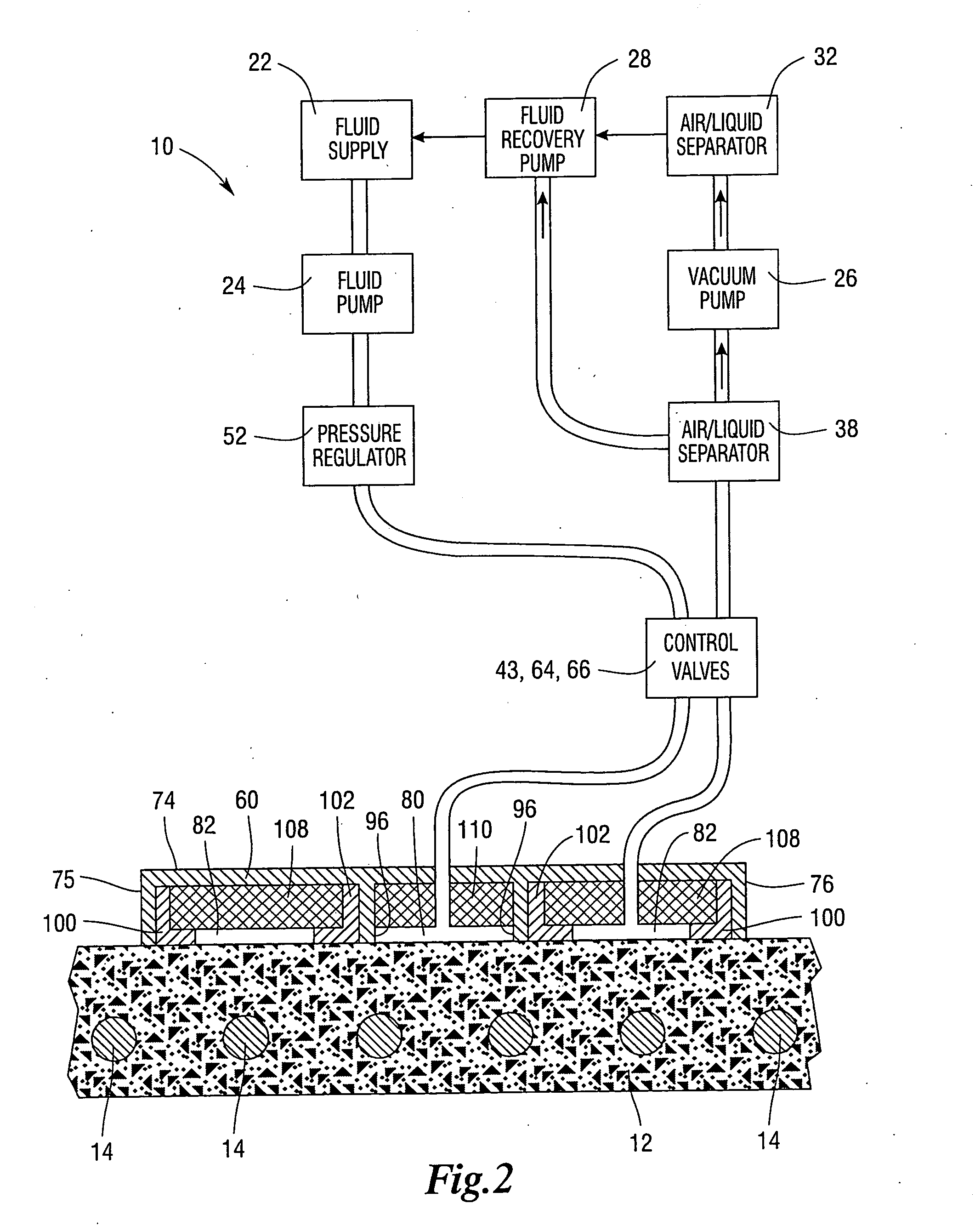
[0012]The non-invasive method of the present invention is for treating by injecting a fluid treatment material such as a liquid preservative into a porous structure such as those formed from masonry, concrete, brick, stone, marble, and wood including those structures having reinforcement members or other members embedded therein, whether those structures are situated in the atmosphere or under water. Typical of the structures treatable by the method of the invention would be sidewalks, airport runways, parking garages, building walls and ceilings, bridge decks, bridge piers, tunnels, roof decks, balconies, monuments, statues, sea walls, containment dikes, foundations and such like. The non-invasive method of this invention in its preferred form includes the steps of engaging in sealed relationship to a porous structure to be treated an applicator head of the present invention having defined therein at least one outer first chamber and at least one inner second chamber within the confines of the first chamber, the chambers sealed from each other, with the chambers communicating with the structure to be treated; drawing a vacuum on each of the chambers to secure the applicator head to the structure; withdrawing the vacuum from the inner second chamber; supplying a pressurized fluid treatment material such as a liquid preservative to the inner second chamber and the structure to be treated until the structure is impregnated with the preservative material to a desired depth and; while supplying the treatment material maintaining the drawing vacuum on the outer first chamber and continuing supplying the preservative material to the inner second chamber to keep the applicator head in sealed engagement with the structure. Securing the applicator head in place on the structure with the applicator head sealed from the surrounding environment permits the treating of any structure whether it is located in the atmosphere or under water, or whether it is upright, such as a vertical wall, a ceiling, or a typical horizontal structure, such as a runway, walkway, bridge deck, and such like. The pressurized treatment material is applied after vacuum is removed from the inner second chamber and is applied in a contained setting avoiding splattering or bouncing of the material from the surface of the structure, or its running down from upright structures. The removal of the vacuum and applying pressurized treatment material allows for deeper penetration of the treatment material into the porous structures. The containing and focusing of the pressurized preservative on the structure results in rapid, effective impregnation of the structure with virtually no waste of the material. Typical negative pressure or vacuum to be applied in the treating process would be between 25 and 27 mmHg with the pressure of the treating material being between 10 and 15 lbs / sq. in. Lower vacuum and higher treatment material pressure could also be applied in certain conditions of the structure to be treated.
[0014]The basic method of treating porous structures of the present invention is simple, easy to understand, easily controlled, and rapid in operation. The basic structure of the apparatus of this invention is simple in construction, comprised of few elements, relatively inexpensive to produce utilizing standard components, and uncomplicated and efficient in its use. This apparatus is modifiable in various ways, for example in the types of pumps, containment vessels, and control arrangement, as well as differing shapes and sizes of applicator heads.

Problems solved by technology

These outdoor structures are exposed to the environment including water and various hazards from atmospheric pollutants and conditions such as acid rain, salt, extremes of temperature and other airborne and water pollutants.
Reinforcing steel members embedded in the porous structures increase deterioration created by the corrosion and oxidation of the steel following erosion of the surrounding material caused by the pollutants in the atmosphere and water.
The pollutants, acid in character, penetrate and react with the salts present in the material resulting in slow and persistent erosion, cracking, crumbling, spaulling, and eventual failure of the exposed porous structures.
Preservative materials applied by brush, spray, roll-on, and even pressure injection methods, achieves only shallow penetration by capillary action.
A single coating of the preservative material proved insufficient with a second coating tending to clog the porous structure's breathing passages according to the National Bureau of Standards Report No. 1118.
With the surfaces of the porous structures clogged, internal stresses and pressures develop within, created by the effect of thermal changes on the ever-present moisture in masonry.
As a result, the trapped vapor pressure generated thereby breaks through and cracks, delaminates, and destroys the protective coating.
No known success has been evidenced with the Klein et al process.
These preservation methods are slow, tedious, costly, and oftentimes somewhat ineffective.
Damage often results to the original coating from the shallow penetration and sealing effect of applications made by brush, roll-on or spray.
The presently used methods of preservation and treating porous structures are inadequate in providing deep impregnation of treating liquids into the structure.
Additionally, the methods and treating apparatus cannot be used effectively on all structures.
Typically, brushing, rolling, spraying, or pressure injecting treating liquid on vertical structures is seriously ineffective since those methods rely on gravity and capillary action to move the liquids into the structure.
Although concentrated pressure injecting of treating liquids into a structure or substrate results in some degree of impregnating, the methods used are limited in that they are useable with structures such as construction lumber, utility poles, and certain portable concrete structures where the various structures are placed in a fixed tank and subjected to pressurized treating liquids.
These pressure systems are not useable on outdoor structures of the kinds already mentioned.
Apparatus for injecting preservative liquids into porous structures are limited to use on flat, horizontally oriented structures such as floors, roads, walkways, tunnel and bridge surfaces, runways, and such like.
Spraying treatment material also results in the bouncing of the liquid as it hits the surface of the structure resulting in unnecessary waste of the treatment material.
Aside from not being useable on upright or vertical oriented structures, the known pressure injection apparatus is not useable under water or on ceilings.

Method used


Image

  • Apparatus and method for treating and impregnating porous structures
  • Apparatus and method for treating and impregnating porous structures
  • Apparatus and method for treating and impregnating porous structures

Examples


Embodiment Construction

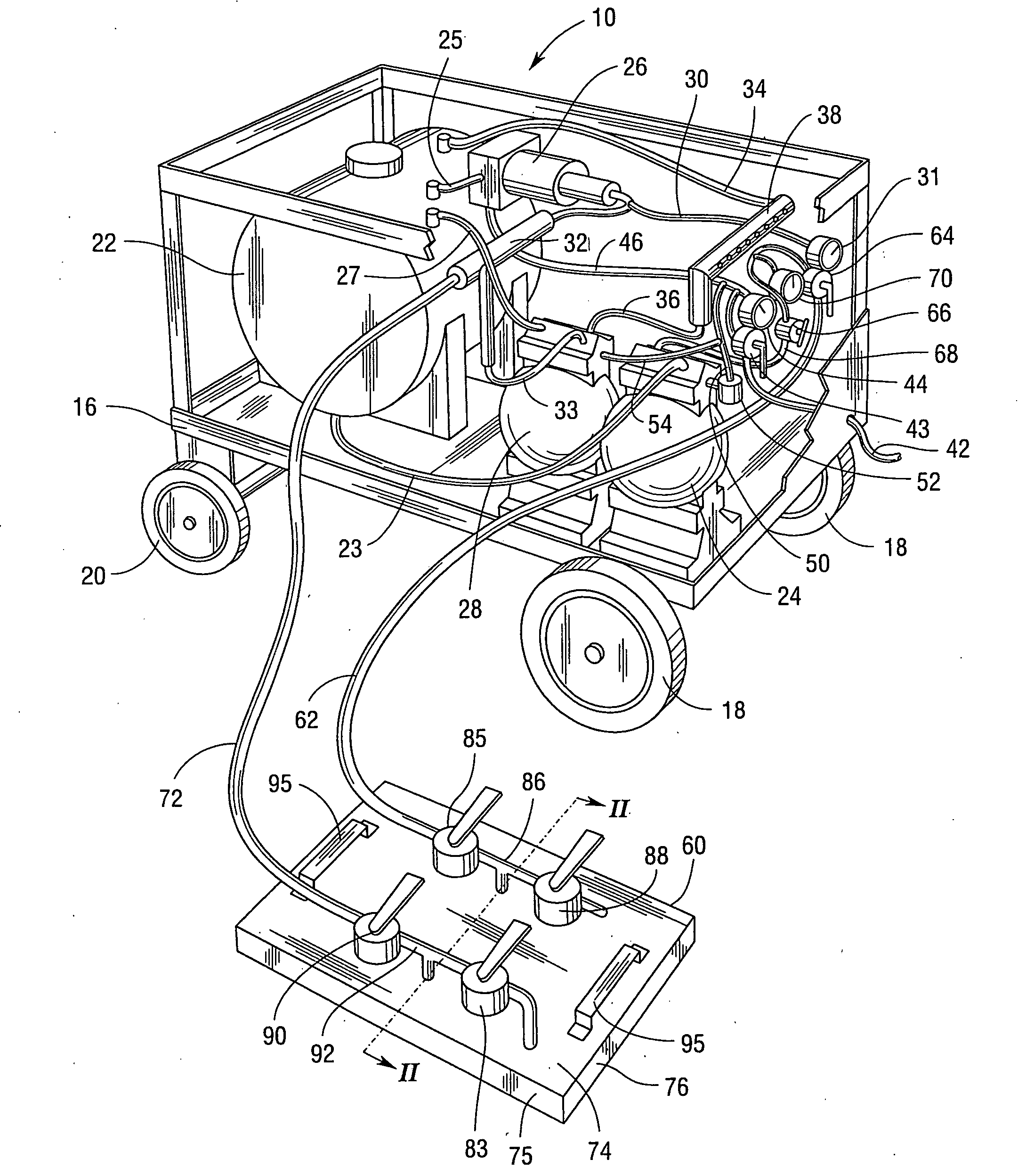
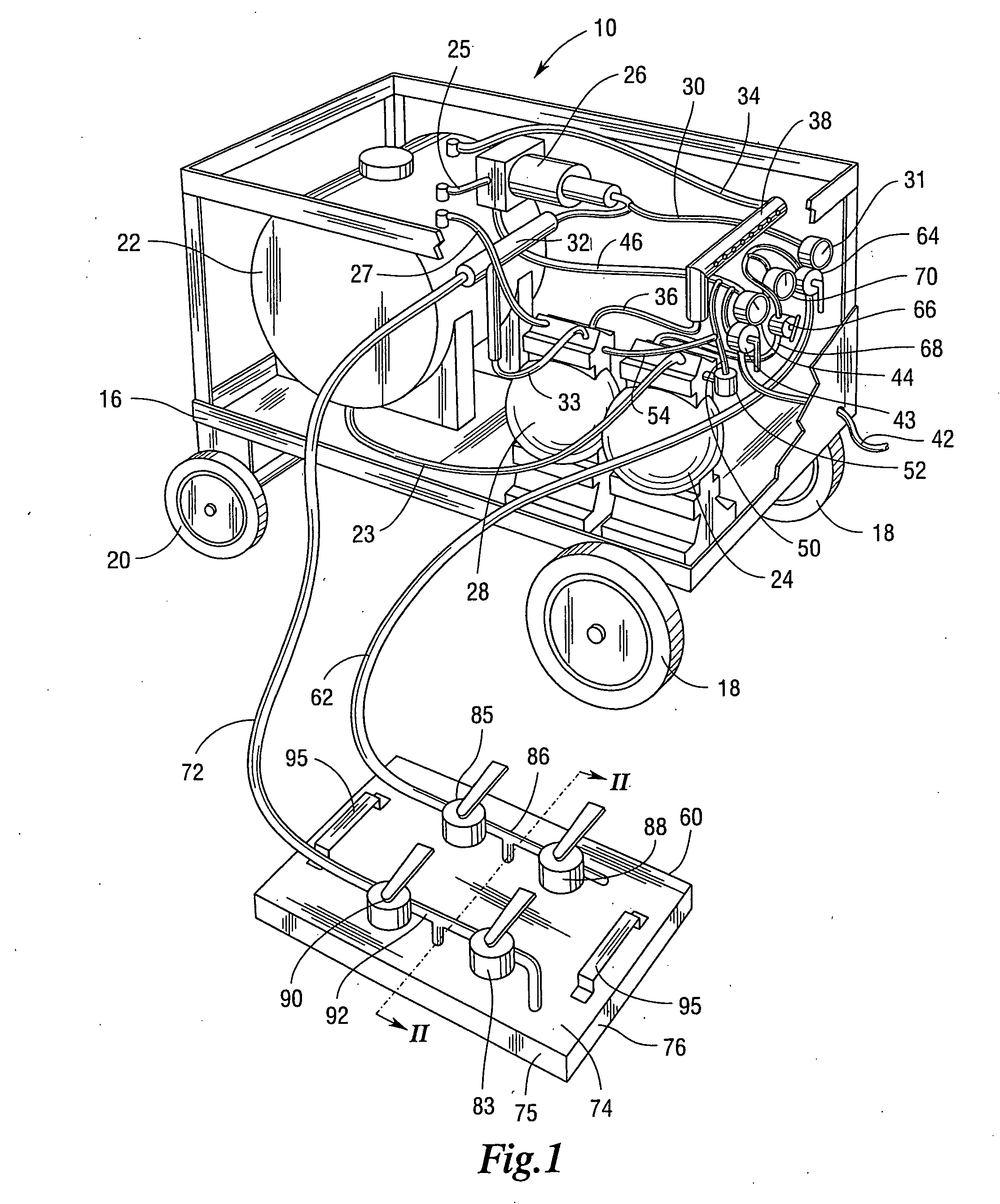
[0029]Referring now to the drawing there is shown an apparatus 10 for treating a porous structure formed from concrete, masonry, brick, stone, marble, or wood including those structures with reinforcement members or other members embedded therein. Typical of such porous structures are building parts, roads, bridges, airport runways, marine supports, monuments, sculptures, art works, and various other man made outdoor structures. The apparatus and method of the present invention are useable to treat structures in the atmosphere or under water, and structures which are upright, such as walls, and ceilings. FIG. 2 shows a section of a porous concrete structure 12 which could be typically a building floor, roadbed, walkway, or an airport runway, having embedded therein steel reinforcing rods 14. The apparatus 10 would be used for treating the porous structure 12, apparatus 10, as shown in the various figures, includes a portable frame or carriage 16 which may be moved from place to plac...


PUM

PropertyMeasurementUnit
pressuresaaaaaaaaaa
pressuresaaaaaaaaaa
pressureaaaaaaaaaa

Abstract

Apparatus and method for treating by injecting a fluid treatment material into the bodies of porous structures such as those formed from concrete, brick, stone, marble, and wood. The apparatus for use in the method includes an applicator head having an inner chamber and an outer chamber surrounding the inner chamber both of which chambers are connected with a vacuum source. The inner chamber is also connected with a source of pressurized liquid treatment material. The method is non-invasive in that the fluid treatment material impregnates the porous structure without the need to break open, destroy, repair, or replace any part of the structure, and includes the steps of engaging the structures with the applicator head, drawing a vacuum on at least the outer chamber to secure the applicator head to the structure, and supplying the pressurized liquid treatment material to the inner chamber to and onto the surface of the structure to impregnate the structure to be treated.

Description

RELATIONSHIP TO OTHER PATENT APPLICATIONS[0001]This patent application is a Continuation-In-Part Application of U.S. patent application, Ser. No. 10 / 465,224, now U.S. Pat. No. 7,141,118 B2 and pending Divisional Application of U.S. patent application Ser. No. 11 / 499,094, in the name of GERARD J. VAEREWYCK, et al for APPARATUS AND METHOD FOR TREATING AND IMPREGNATING POROUS STRUCTURES, and pending Continuation-In-Part Application Ser. No. 12 / 003,504 in the name of GERARD J. VAEREWYCK for APPARATUS AND METHOD FOR TREATING AND IMPREGNATING POROUS STRUCTURES.BACKGROUND OF THE INVENTION[0002]1. Field of Invention[0003]This invention relates to apparatus and method for treating by injecting a fluid treatment material into the body of porous structures such as those formed from concrete, brick, stone, marble and wood including those structures with metal reinforcement members or other members embedded therein. The method of this invention is non-invasive in that fluid treatment material im...

Claims


Application Information

Patent Timeline
Patent Type & Authority Applications(United States)
IPC IPC(8): B05D3/00C23C16/54
CPCB05D7/06B05D2203/20B27K3/08B27K3/105C04B41/4521E04G23/0203E01C23/06E04F21/08E04F21/12E04G23/02C04B2111/26E04G23/0211
Inventor VAEREWYCK, GERARD J.
Owner VAEREWYCK GERARD J
Learn More