
Method and system for swipe sensor image alignment using fourier phase analysis

a swipe sensor and phase analysis technology, applied in image analysis, image enhancement, instruments, etc., can solve the problems of non-uniform illumination, background noise, non-uniform illumination, etc., and achieve the effect of precise determination of x and noise immunity

Inactive Publication Date: 2009-07-09
SONAVATION INC
View PDF8 Cites 13 Cited by
  • Summary
  • Abstract
  • Description
  • Claims
  • Application Information

AI Technical Summary

Benefits of technology

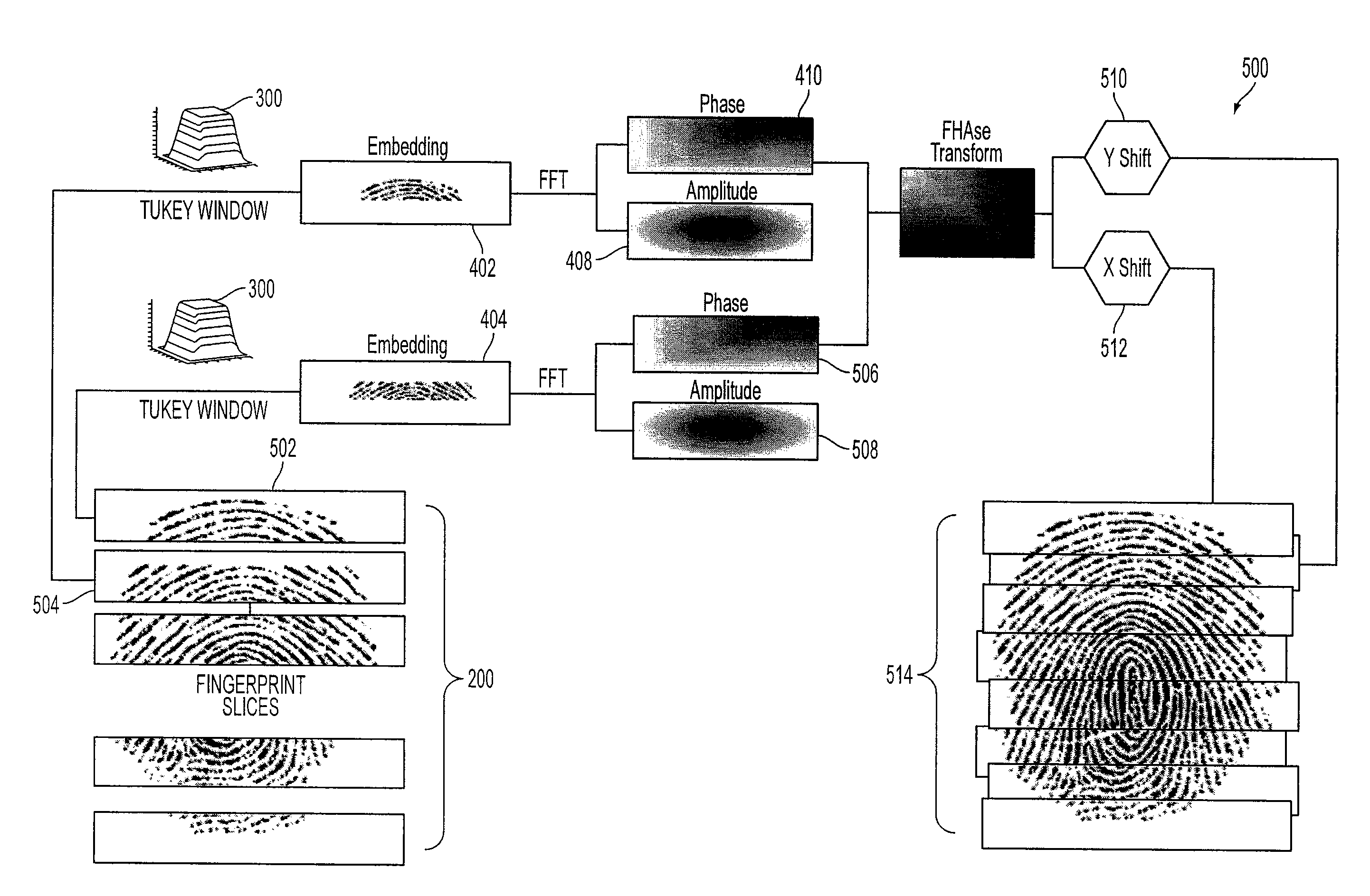
[0011]The present invention provides a unique approach for finding a relative shift in spatial domain in x and y directions between two partial images, particularly biometric images such as fingerprints. More specifically, the present invention provides a means to determine precise x and y coordinates, with a level of noise immunity, without the need to perform correlations. Precisely determining the extent of the x and y shifts between two successive partial images is fundamental to an accurate and seamless construction of an entire fingerprint reconstructed from all of the partial images.
[0012]The techniques of present invention virtually ignore background illumination problems. For example, if a background image associated with a fingerprint is gray or dark, this gray or dark background image, which could be mistakenly represented by ridges surrounding the fingerprint, is ignored. This process aids in a more precise determination of the x and y shifts.

Problems solved by technology

Both of these conventional image registration techniques, however, suffer shortcomings.
For example, conventional techniques are susceptible to background noise, non-uniform illumination, or other imaging artifacts.

Method used


Image

  • Method and system for swipe sensor image alignment using fourier phase analysis
  • Method and system for swipe sensor image alignment using fourier phase analysis
  • Method and system for swipe sensor image alignment using fourier phase analysis

Examples


Embodiment Construction

[0023]This specification discloses one or more embodiments that incorporate the features of this invention. The embodiment(s) described, and references in the specification to “one embodiment”, “an embodiment”, “an example embodiment”, etc., indicate that the embodiment(s) described may include a particular feature, structure, or characteristic, but every embodiment may not necessarily include the particular feature, structure, or characteristic. Moreover, such phrases are not necessarily referring to the same embodiment. Furthermore, when a particular feature, structure, or characteristic is described in connection with an embodiment, it is submitted that it is within the knowledge of one skilled in the art to effect such feature, structure, or characteristic in connection with other embodiments whether or not explicitly described.

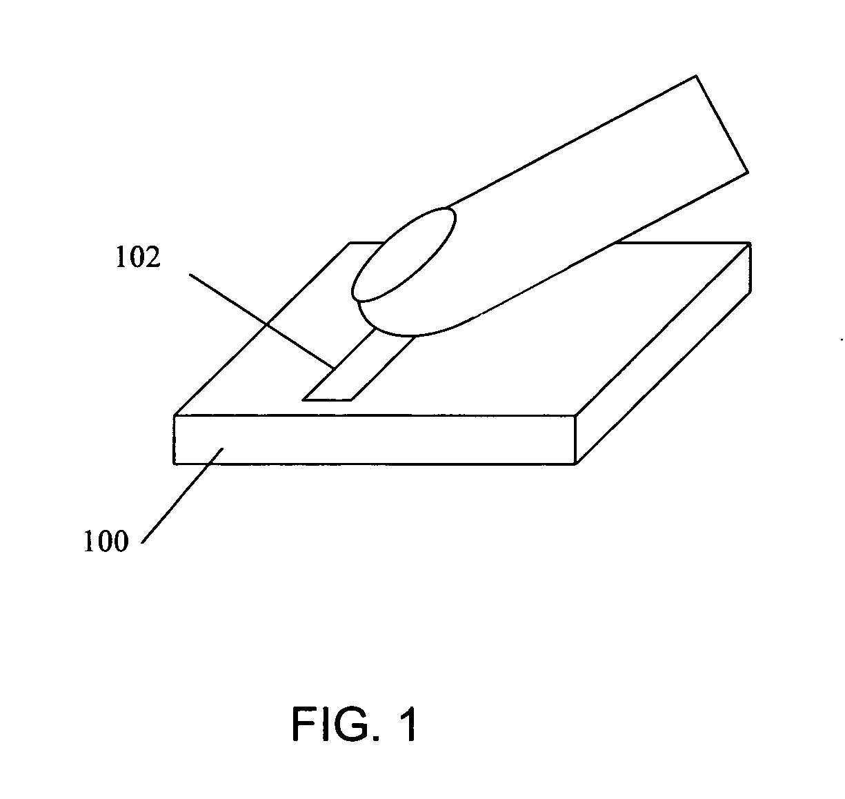
[0024]FIG. 1 is an illustration of a conventional swipe-style biometric sensing device 100 according to embodiments of the present invention. In FIG. 1, ...


PUM


Abstract

Provided is a method for analyzing image slices. The method includes transforming a first slice and a second slice to frequency domain and determining shift data between the first slice and the second slice from only the phase component of the transformed first and second slices.

Description

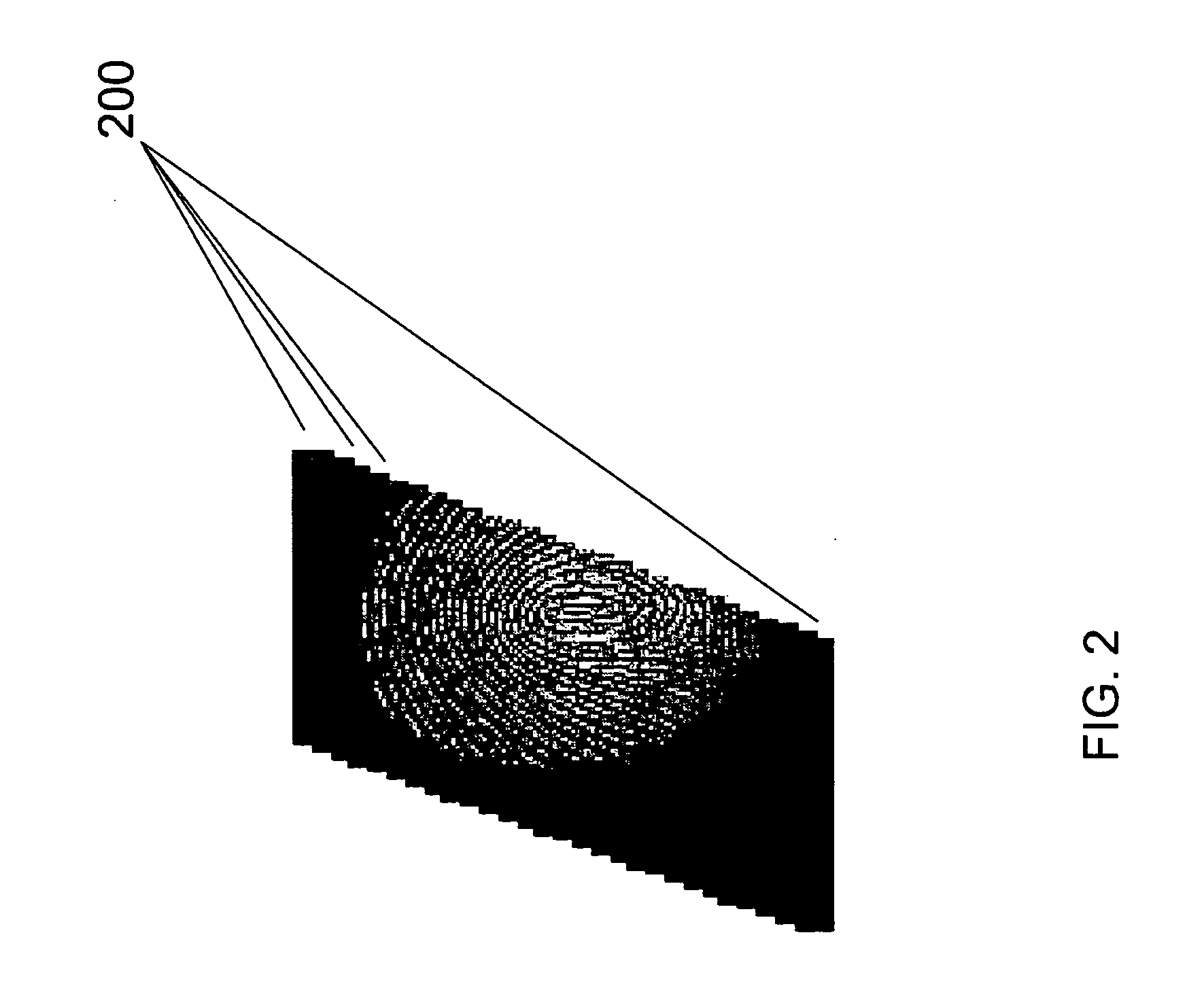
BACKGROUND OF THE INVENTION[0001]1. Field of the Invention[0002]The present invention relates to image alignment. More particularly, the present invention relates to aligning partial images produced by swipe-style biometric sensing devices.[0003]2. Related Art[0004]In the field of biometric image analysis, traditional techniques sample an image, such as a fingerprint, as the image is moved or swiped across a sensing mechanism. This sensing mechanism, which could be a fingerprint sensor, captures partial images of the finger during a single swipe. This single swipe produces sets of data at different times and within different coordinate systems. Computer vision technology can then be used to reconstruct an image on the entire fingerprint by sampling these sets of data and combining the partial images to form a complete image of the fingerprint.[0005]The process of transforming these different sets of data into one coordinate system is known to those of skill in the art as image regis...

Claims


Application Information

Patent Timeline
Patent Type & Authority Applications(United States)
IPC IPC(8): G06K9/00
CPCG06K9/00026G06T2207/20056G06T2207/10016G06T7/0036G06T7/37G06V40/1335G06F18/00
Inventor JAHROMI, OMID S.
Owner SONAVATION INC
Learn More