
Active noise controller

a technology of active noise controller and noise reduction, which is applied in the direction of noise generation, ear treatment, instruments, etc., can solve the problems of increasing the operation load, reduce the operation load, reduce the noise at the error signal detector, and minimize the number of times of executing product operations.

Inactive Publication Date: 2009-07-09
PANASONIC CORP
View PDF1 Cites 50 Cited by
  • Summary
  • Abstract
  • Description
  • Claims
  • Application Information

AI Technical Summary

Benefits of technology

[0010]The present invention provides an active noise controller reducing the operation load required for noise-canceling control by minimizing the number of times of executing product operations.
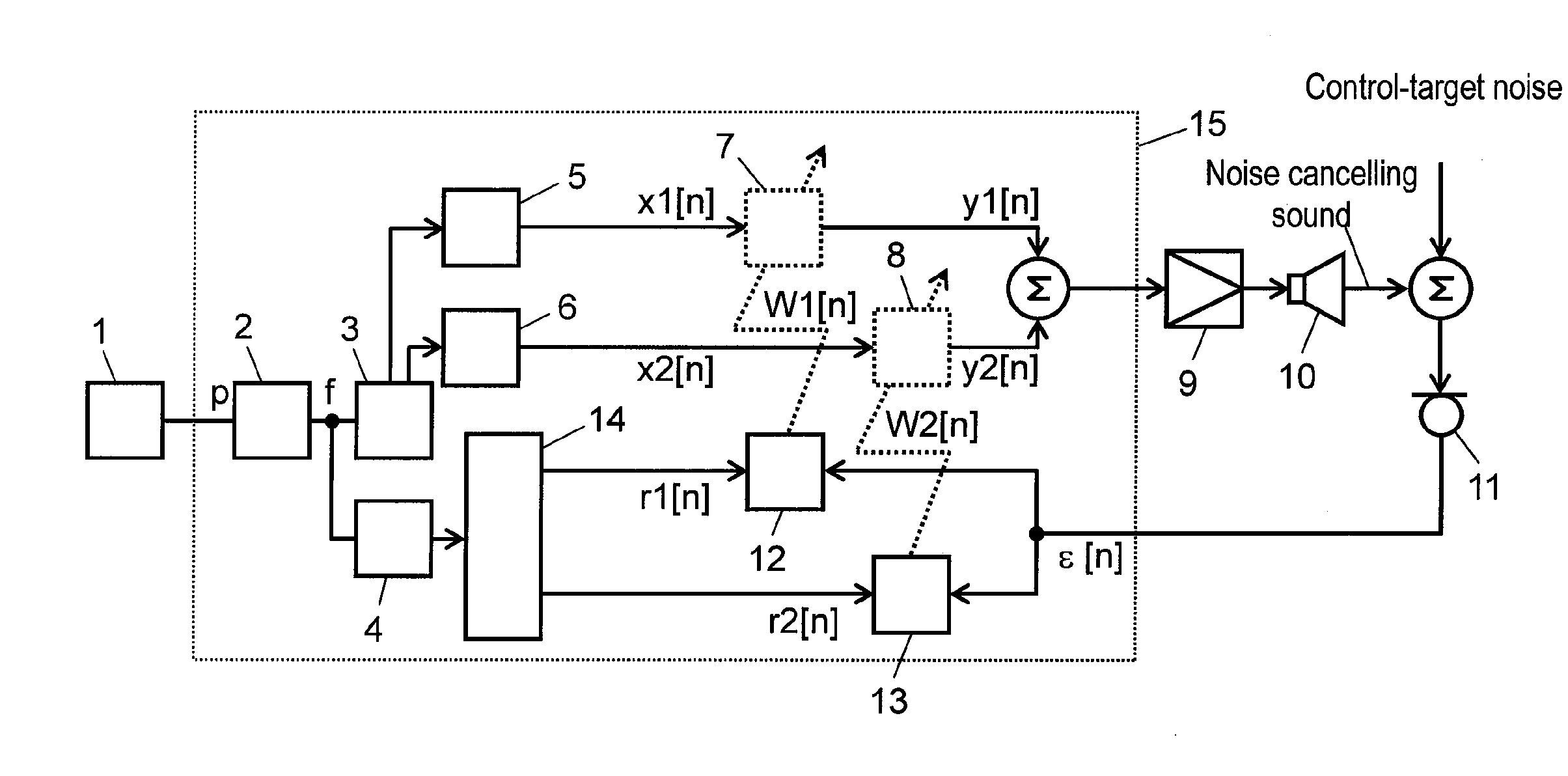
[0011]An active noise controller of the present invention is composed of a control-target noise frequency detector detecting the frequency of noise to be controlled caused by a noise source; a sine wave generator generating a sine wave with its frequency same as that of noise detected by the control-target noise frequency detector; a cosine wave generator generating a cosine wave with its frequency same as that of noise detected by the control-target noise frequency detector; a first one-tap digital filter into which a sine-wave signal from the sine wave generator is input; a second one-tap digital filter into which a cosine-wave signal from the cosine wave generator is input; a drive signal generator into which data produced by adding output from the first one-tap digital filter to the second one is input, to output a drive signal to make interfere with noise to be controlled caused by a noise source; an error signal detector detecting an error signal caused by the interference between a drive signal output from the drive signal generator and noise to be controlled caused by a noise source; a first coefficient updater updating the filter coefficient of the first one-tap digital filter; and a second coefficient updater updating the filter coefficient of the second one-tap digital filter. The first and second coefficient updaters update the coefficients of the first and second one-tap digital filters so that noise at the error signal detector is reduced, according to an error signal from the error signal detector and the respective reference signals for an isosceles triangle wave with its basic frequency same as that of noise detected by the control-target noise frequency detector.
[0012]In this way, when the reference signal is an isosceles triangle wave, a value related to the phase characteristic of the transmission characteristic of from the drive signal generator to the error signal detector is determined without a product operation required. Hence, the operation load is reduced.
[0013]When the reference signal is a square wave or isosceles trapezoid wave, the operation load is reduced as well.

Problems solved by technology

In the above-described conventional configuration, however, generating reference sine-wave signal r1[n] and reference cosine-wave signal r2[n] involves a product-sum operation of reference sine-wave signal x1[n] with reference sine-wave signal correction value C1[f] and that of reference cosine-wave signal x2[n] with reference cosine-wave signal correction value C2[f], requiring two times of product operations to produce respective reference signals, which increases the operation load.

Method used


Image

  • Active noise controller
  • Active noise controller
  • Active noise controller

Examples


first exemplary embodiment

[0043]Hereinafter, a description is made for an active noise reduction apparatus according to the first exemplary embodiment of the present invention, with reference to the related drawings.

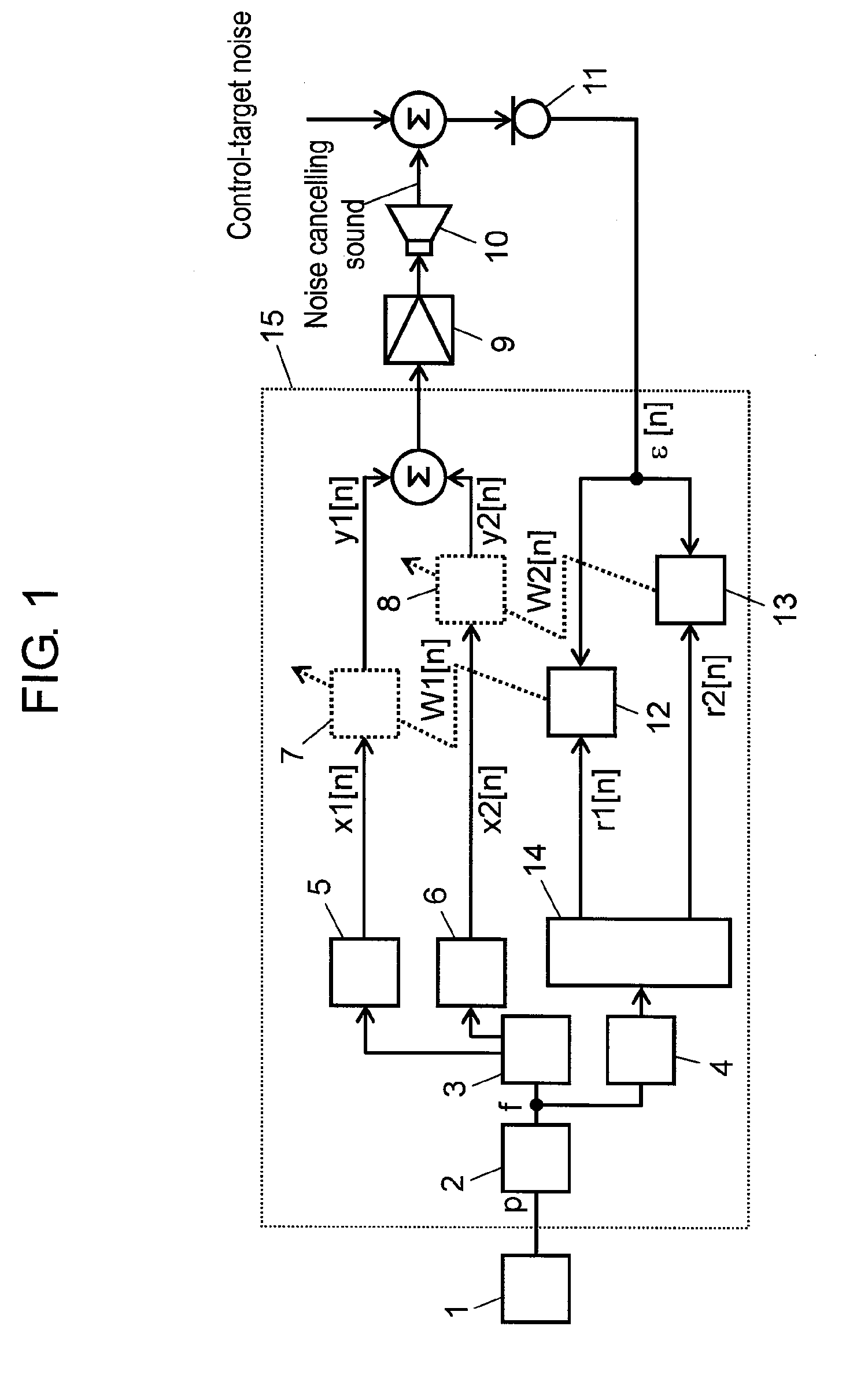
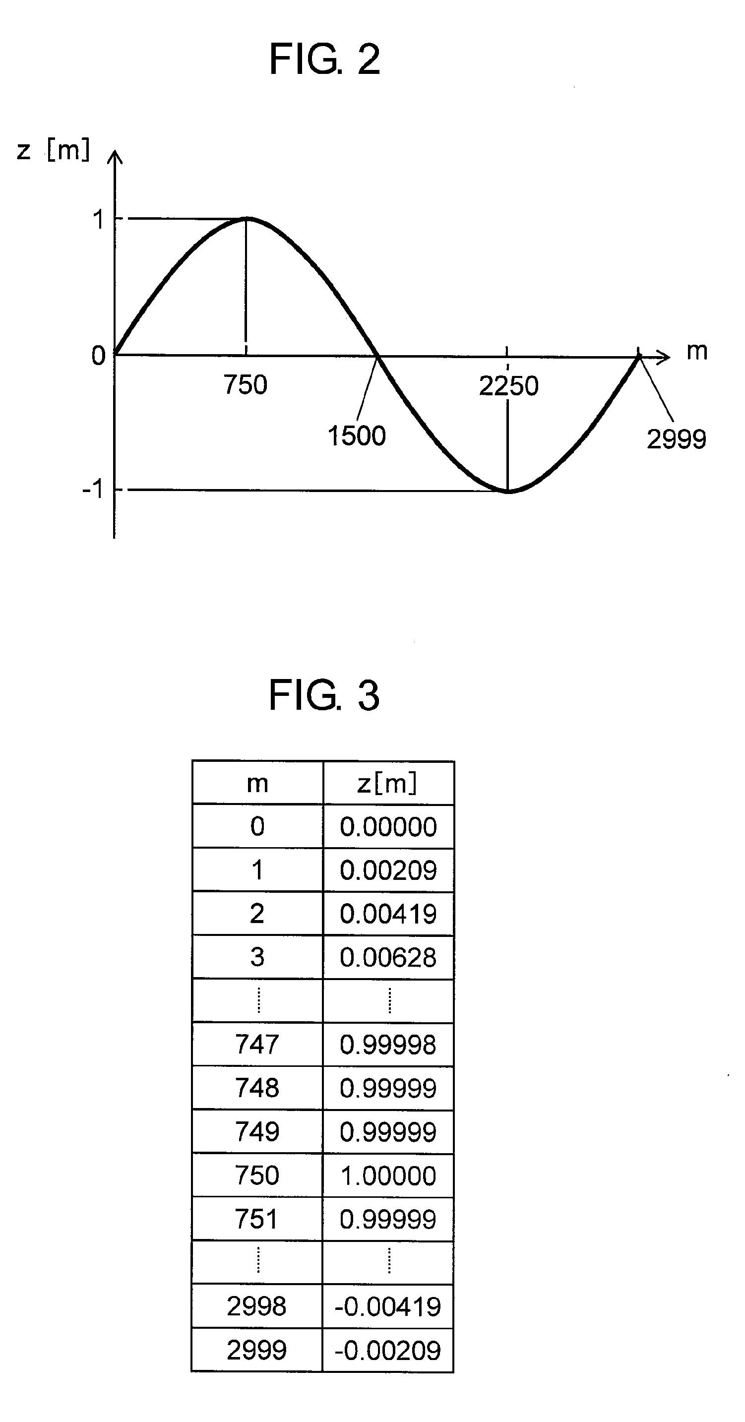
[0044]FIG. 1 is a block diagram of an active noise reduction apparatus according to the first embodiment of the present invention. In FIG. 1, engine rotation speed detector 1 outputs a pulse string with its frequency proportional to the rotation speed of the engine (i.e. a noise source incorporated into a vehicle) as engine pulses p. Frequency detector 2 (i.e. control-target noise frequency detector) calculates control-target noise frequency f (Hz) from engine pulses p and outputs the frequency. Sine wave table 3 including sine wave data discretized retains on a memory sine values at respective points given by equally dividing one cycle of sine wave by N.

[0045]Sine wave generator 5 reads data from sine wave table 3 at every sampling cycle at given intervals according to control-target noise frequ...


PUM


Abstract

In an active noise reduction apparatus with an adaptive notch filter used, a triangle wave as a reference signal input into a first coefficient updater and a second coefficient updater reduces the number of execution times of product-sum operations in a reference signal generator to reduce the operation load.

Description

TECHNICAL FIELD[0001]The present invention relates to an active noise reduction apparatus actively reducing vibration noise generated from a rotating machine such as an engine on a vehicle.BACKGROUND ART[0002]In a conventional active noise reduction apparatus, a method is known of performing adaptive control with an adaptive notch filter (refer to patent literature 1 for example).[0003]FIG. 7 is a block diagram illustrating the configuration of a conventional active noise reduction apparatus described in patent literature 1. In FIG. 7, a discrete operation for implementing an active noise reduction apparatus is executed by discrete operation processing unit 115. Engine rotation speed detector 101 outputs as engine pulses p, a pulse string with its frequency proportional to the rotation speed of the engine. Engine pulses p are produced by extracting output from a crank angle sensor, for example. Frequency detector 102 calculates noise frequency f according to engine pulses p and outp...

Claims


Application Information

Patent Timeline
IPC IPC(8): G10K11/16
CPCG10K11/1788G10K2210/3053G10K2210/3028G10K11/17854G10K11/17883
Inventor NAKAMURA, YOSHIOFUNAYAMA, TOSHIYUKIMATONO, TSUKASA
Owner PANASONIC CORP
Learn More