
Method and device for determining state of health of the battery, and battery power supply system

a battery and state of health technology, applied in the direction of instruments, nuclear elements, digital computer details, etc., can solve the problems of heavy operational load, achieve the effect of reducing operational and processing load, reducing operational load, and reducing function

Active Publication Date: 2010-08-31
FURUKAWA ELECTRIC CO LTD
View PDF26 Cites 33 Cited by
  • Summary
  • Abstract
  • Description
  • Claims
  • Application Information

AI Technical Summary

Benefits of technology

This approach allows for precise determination of battery health with reduced operational and processing loads, enabling the use of lower-function CPUs and lowering costs, while maintaining the same level of precision as traditional impedance-based methods.

Problems solved by technology

However, any one of the conventional method for determining state of health of the battery requires high level of trigonometric function to calculate the internal impedance so that a high performance CPU with higher cost is required to implement the calculation which results in a heavy operational load, thus causing problem.

Method used


Image

  • Method and device for determining state of health of the battery, and battery power supply system
  • Method and device for determining state of health of the battery, and battery power supply system
  • Method and device for determining state of health of the battery, and battery power supply system

Examples


first embodiment

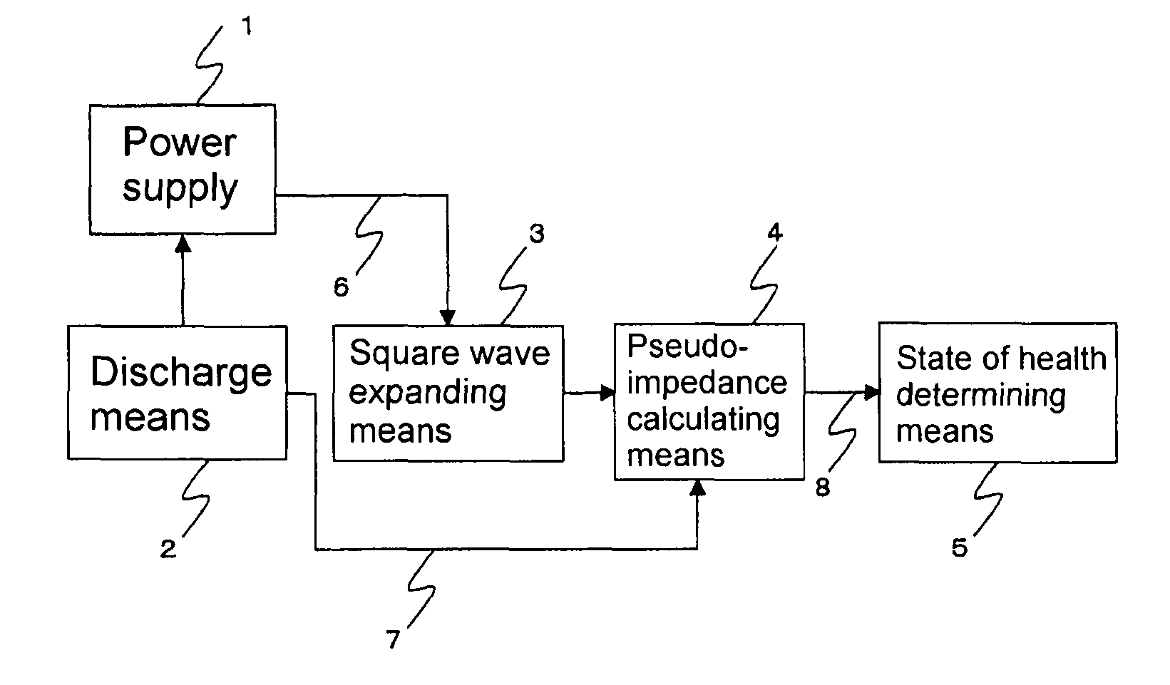
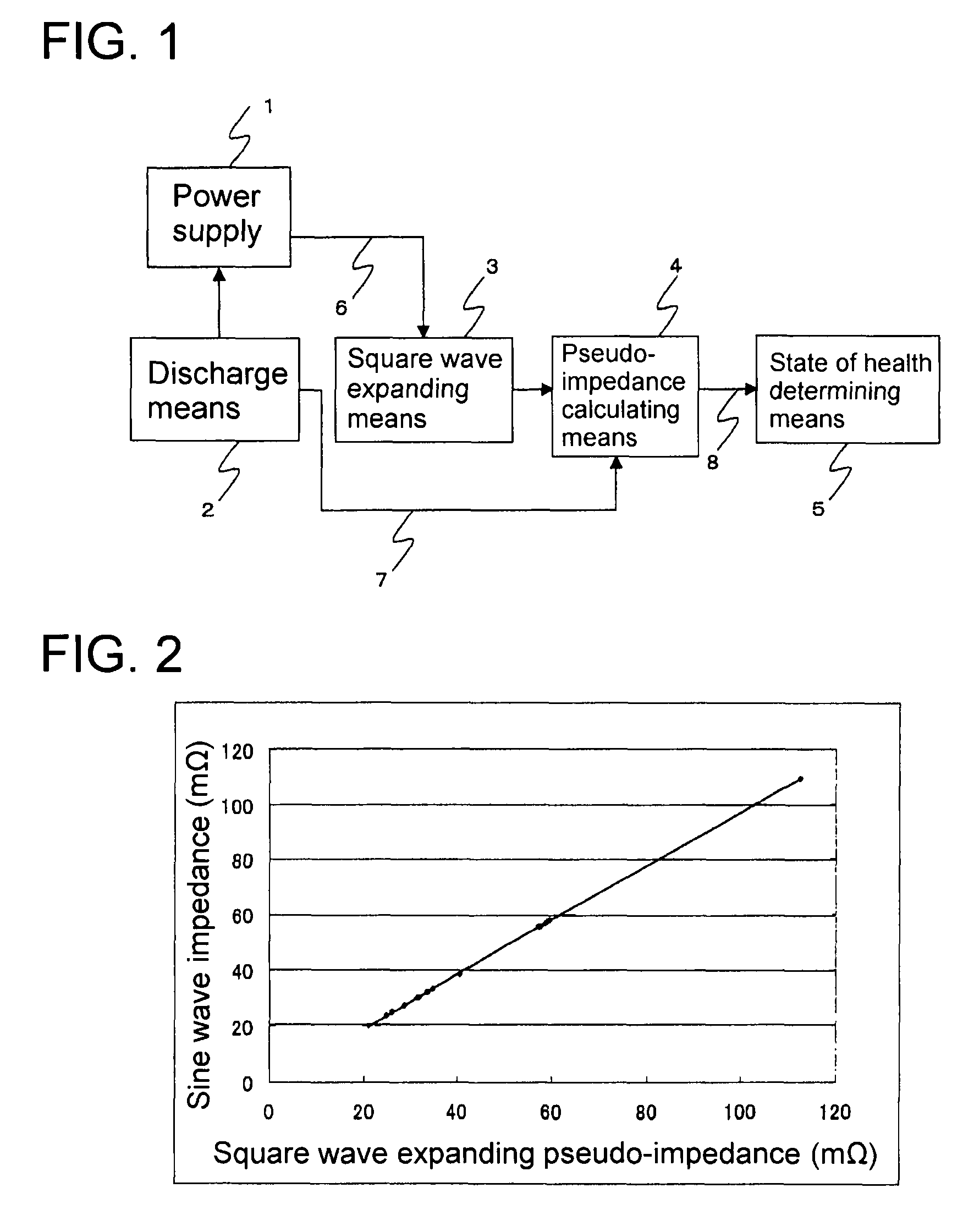
[0050]FIG. 1 is a block diagram depicting the method for determining state of health of the battery of the invention. The discharge means 2 causes the battery 1 to discharge square wave pulses with a prescribed cycle at the prescribed current value 7. This can be easily realized by opening and closing the switch in the prescribed cycle.

[0051]The square wave expanding means 3 implements sampling of the response voltage 6 when the battery 1 is caused to pulse-discharge by the discharge means 2, and expands into the orthogonal square wave components. The orthogonal square wave is expressed in general by the followings:

[0052]f⁡(nt)={1⁢:⁢⁢m·(T / n)≦t(m+1 / 2)·(T / n)-1⁢:⁢⁢(m+1 / 2)·(T / n)≦t(m+1)·(T / n)(equation⁢⁢1)g⁡(nt)={-1⁢:⁢⁢m·(T / n)≦t(m+1 / 4)·(T / n)1⁢:⁢⁢(m+1 / 4)·(T / n)≦t(m+3 / 4)·(T / n)-1⁢:⁢⁢(m+3 / 4)·(T / n)≦t(m+1)·(T / n)(equation⁢⁢2)

[0053]Where, T is the cycle of the fundamental wave (i.e., the wave with the lowest frequency), and equal to the cycle of the pulse discharge, n is the natural number minus (...

second embodiment

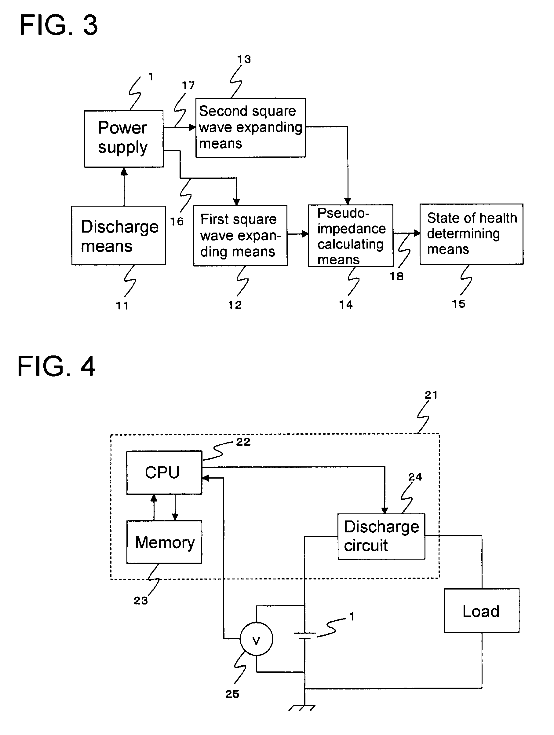
[0065]the method for determining state of health of the battery of the invention is described with reference to FIG. 3. In this embodiment, the pulse discharge with arbitrary waveform is applied to determine state of health of the battery, in place of the pulse discharge with the square wave.

[0066]The discharge means 11 causes the battery 1 to pulse-discharge with a prescribed waveform. The above-described prescribed waveform can be arbitrarily prepared and applied. The arbitrarily prepared waveform can be set in advance in the discharge means 11. The square wave can be surely used as the arbitrary waveform.

[0067]The first square wave expanding means 12 implements sampling of the response voltage 16 when the battery 1 is caused to pulse-discharge by the discharge means 11, and expands into the orthogonal square wave component. Here, the square wave expanding means 12 calculates, for example, the coefficient a1′ (the coefficient a1 in the first embodiment) in the fundamental frequenc...


PUM


Abstract

A method and the device are provided for determining state of health of the battery, in addition to the power supply system using the device, to reduce operational and processing load by expanding the data sampled at the time when the battery is caused to discharge square wave pulses into the square wave is provided. The method includes determining state of health of a battery by causing the battery to discharge square wave pulses with a prescribed cycle at a prescribed current value. Response voltages are sampled at a time of a pulse-discharge. The sampled response voltages are sampled into orthogonal square wave components. An amplitude of the square wave component is divided by the current value of the pulse-discharge to obtain a pseudo-impedance. A state of health of the battery based on the pseudo-impedance is determined.

Description

TECHNICAL FIELD[0001]The present invention relates to a method and device for determining state of health of the battery and a battery power supply system.RELATED ART[0002]Various technologies of the method for determining state of health of the battery have been developed in a rechargeable battery in particular. Among them, the technology to determine state of health of the battery based on a measured internal impedance attracts attention (refer to Patent document 1 listed hereunder, for example). The internal impedance of the battery can be obtained by the followings: Sine wave alternative current is applied to the battery in which neither charge nor discharge is implemented, then a response voltage thereto is detected, and a prescribed arithmetic computation is carried out applying the sine wave alternative current and the response voltage.[0003]For example, Patent document 2 listed hereunder proposes a method for determining state of health of the sealed lead acid battery based ...

Claims


Application Information

Patent Timeline
Patent Type & Authority Patents(United States)
IPC IPC(8): G01R31/36
CPCG01R31/3679G01R31/392
Inventor IWANE, NORIYASUIWAHANA, FUMIKAZUKIMURA, ATSUSHI
Owner FURUKAWA ELECTRIC CO LTD
Learn More