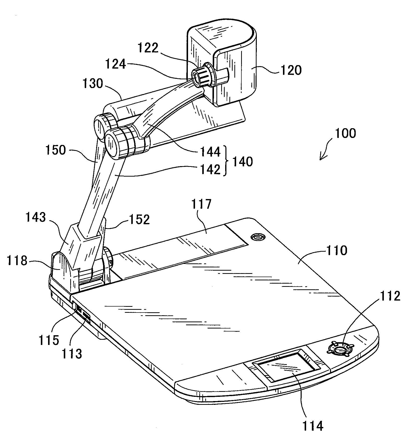
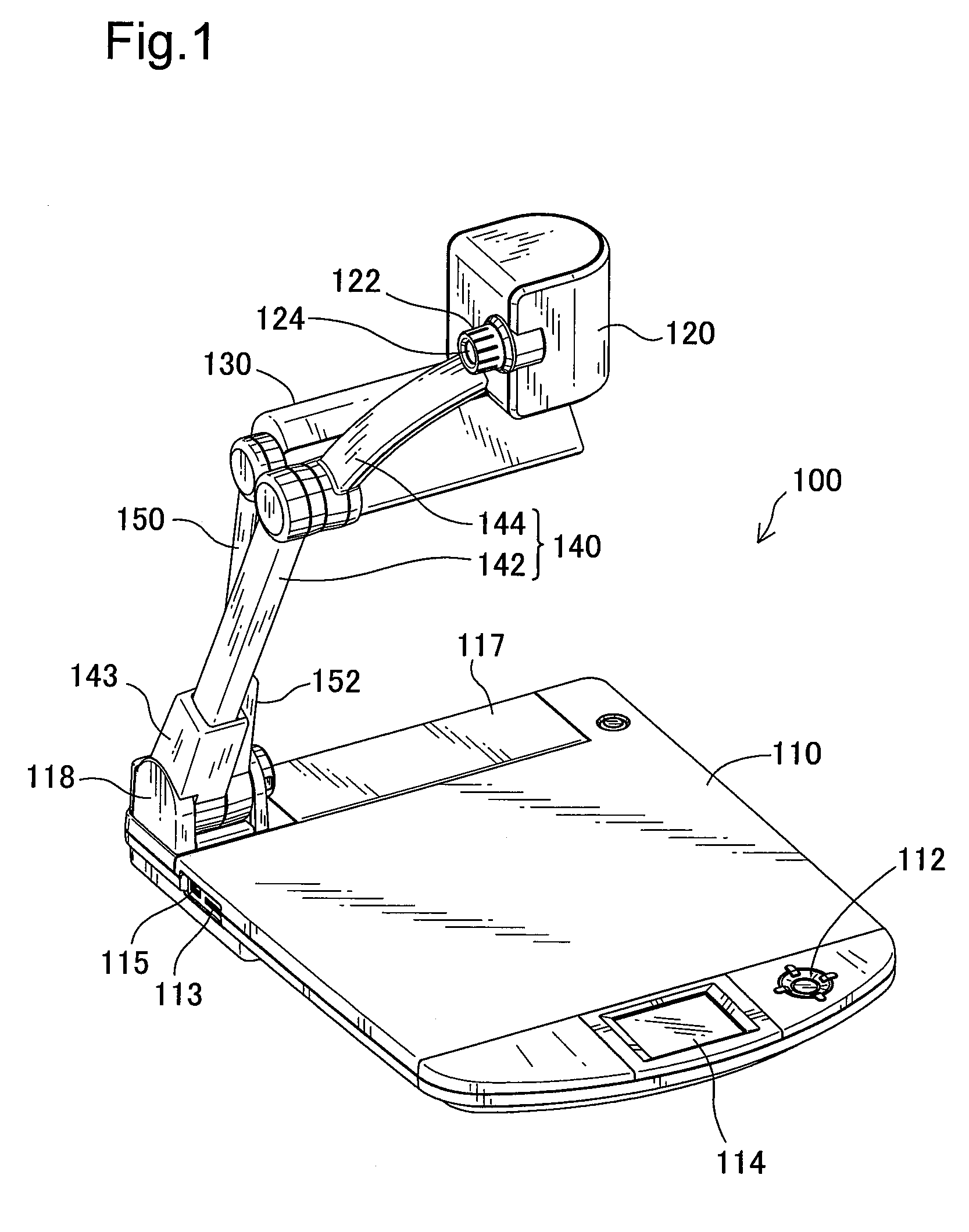
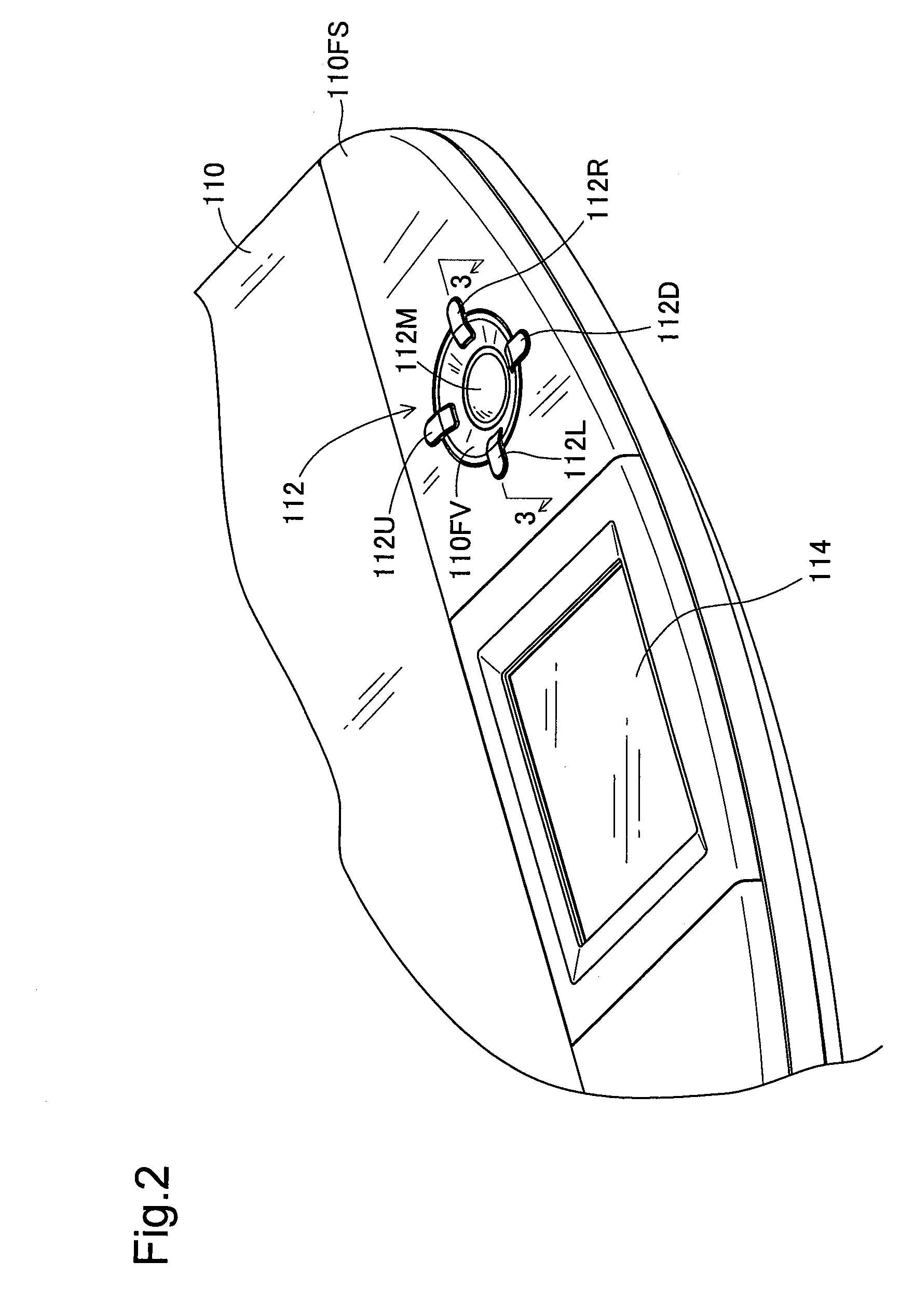
[0007]In order to solve the problem of the prior art explained above, there would be a demand for improving the user's visibility on the device settings and variety of other conditions of the imaging device and thereby enhancing the usability of the imaging device.
[0010]In the imaging device according to this aspect of the invention, the
light emission display module controls the light emission of the
light source to represent the output or non-output of the
camera image to the display unit in a visually recognizable manner. In response to selection of an item of device setting by the operation of the setting operation unit, the processor performs the
processing operation corresponding to the selected item of device setting. The light emission of the light source is also controlled to represent at least one of the working status and completion of each device setting operation as the
processing operation in a visually recognizable manner. The controlled light emission of the light source enables the user of the imaging device to be visually informed of the working status of each device setting operation, as well as the output of the
camera image to the display unit. Such configuration desirably improves the user's visibility on the device settings and enhances the usability of the imaging device. The device setting operation visually represented by the controlled light emission of the light source is preferably a device setting operation that is not visible to the user of the imaging device, for example, a motor operation in an auto focusing process or an
image capture operation of capturing an image and storing a captured image into an
internal memory unit of the imaging device. This arrangement preferably enables the user of the imaging device to be readily notified of the working status and completion of such a device setting operation that is not visible to the user.
[0011]The imaging device according to the above aspect of the invention may adopt any of various arrangements and structures. In one preferable application of the imaging device according to the invention, the light source is designed to allow color modulation, and the light emission display module controls color of light emission of the light source. The emission of different color lights enables the user of the imaging device to be easily informed of the output of the camera image to the display unit and the working status of each device setting operation. This arrangement desirably improves the user's visibility and enhances the usability of the imaging device.
[0012]In one preferable embodiment of the imaging device further has an image input module constructed to input an image. The setting operation unit has an output image setting operation unit operated to set an output image to the display unit to either of the camera image and an external input image input by the image input module. The light emission display module performs different series of light emission controls corresponding to the setting of the camera image to the output image to the display unit and the setting of the external input image to the output image to the display unit through the operation of the output image setting operation unit, so as to make different color lights emitted from the light source. The emission of the different color lights enables the user of the imaging device to be readily informed of every change of the output image to the display unit between the camera image and the external input image. This arrangement effectively improves the usability of the imaging device.
[0013]In one preferable application of the imaging device of this embodiment, the image input module has an image reading module configured to read an image from a storage medium used for storage of the image as the external input image, and an
external image input module configured to input an
external image from an image
output device as the external input image. The output image setting operation unit is operated to set the output image to the display unit to one of the camera image, the read image by the image reading module, and the
external image input by the external image input module. The light emission display module performs different series of light emission controls corresponding to the setting of the camera image to the output image to the display unit, the setting of the read image to the output image to the display unit, and the setting of the external image to the output image to the display unit through the operation of the output image setting operation unit, so as to make different color lights emitted from the light source. The emission of the different color lights enables the user of the imaging device to be readily informed of every change of the output image to the display unit among the camera image, the read image, and the external image. This arrangement effectively improves the usability of the imaging device.
[0015]In the imaging device according to this aspect of the invention, the emission of the different color lights enables the user of the imaging device to be readily informed of every change of the output image to the display unit among the camera image, the read image, and the external image. The imaging device of this configuration informs the user of only the change of the output image to the display unit by the emission of the different color lights. This arrangement also effectively improves the usability of the imaging device.


