
Position sensing display

a technology of sensing display and positioning, applied in the field of positioning sensing display, can solve the problems of reducing reliability, increasing cost, and reducing the number of connections required, and achieve the effect of easing manufacturing

Inactive Publication Date: 2009-07-02
INNOLUX CORP
View PDF10 Cites 48 Cited by
  • Summary
  • Abstract
  • Description
  • Claims
  • Application Information

AI Technical Summary

Benefits of technology

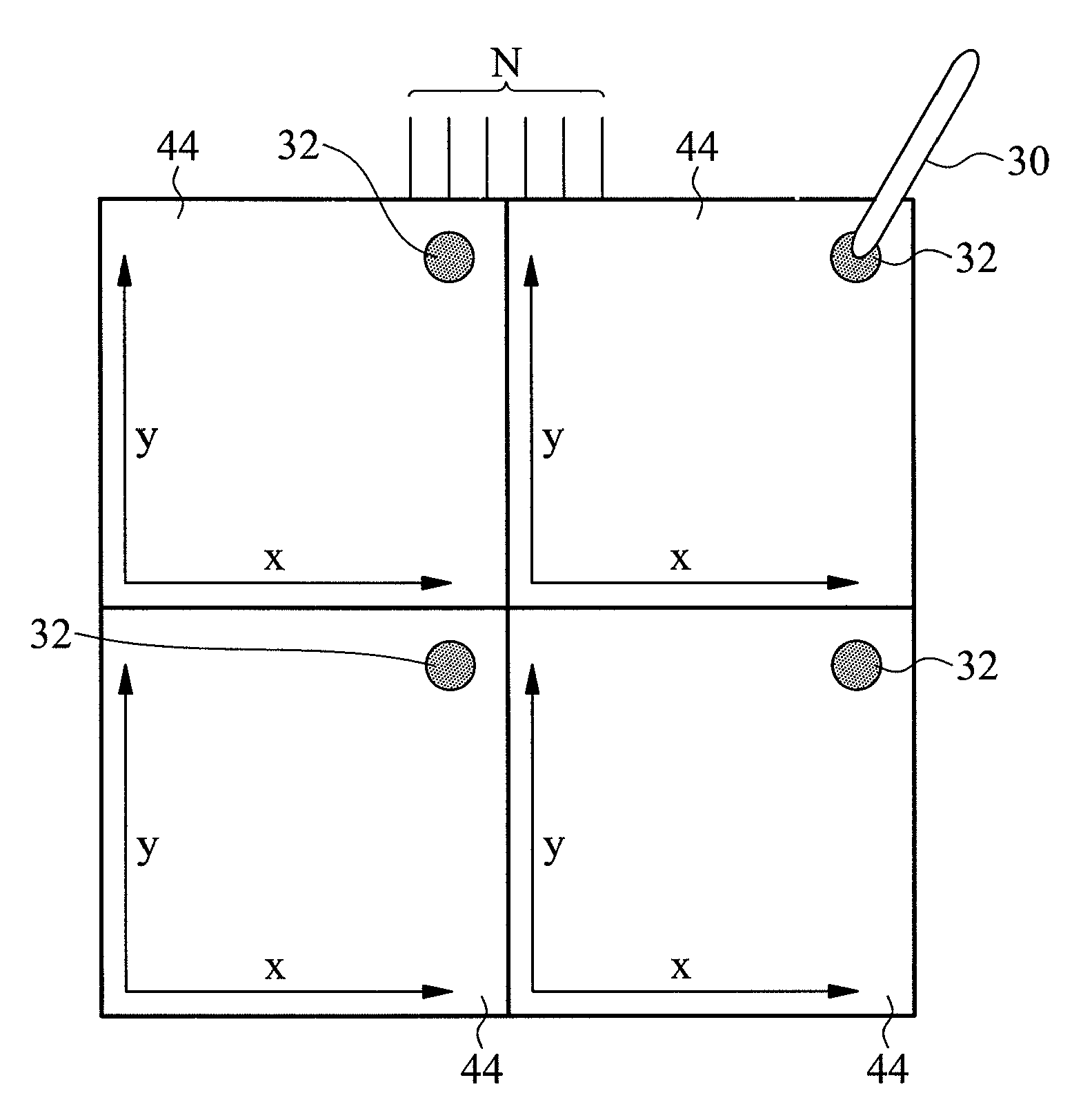
[0013]By combining sensor electrodes together in groups, the increase in the number of connections normally resulting from an increase in resolution is minimised. In spite of a reduced number of connections, improved resolution is still possible.
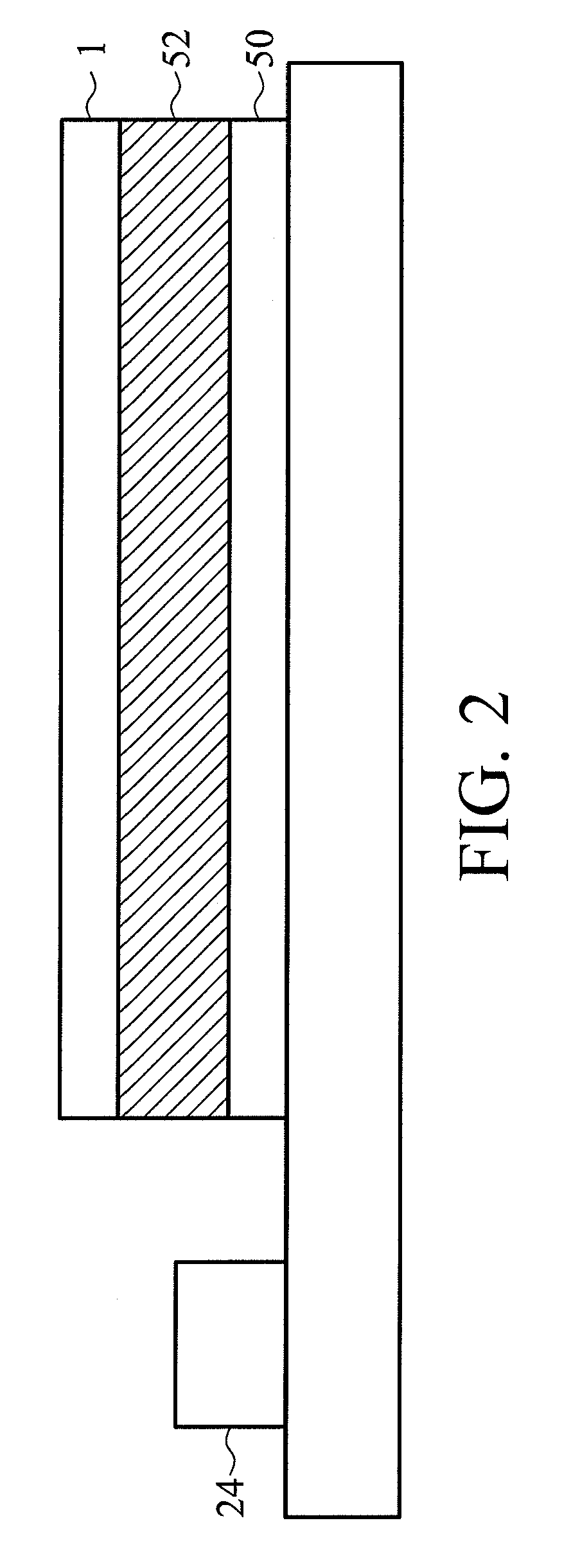
[0015]The display may include an active matrix panel, for example an active matrix liquid crystal display (AMLCD) panel or an active matrix organic light emitting diode display (AMOLED) panel. In this way, all the circuitry and processing can be provided on the active panel and the position sensing electrodes provided on the front panel, which eases manufacture.

Problems solved by technology

However, these sensing electrodes then need to be connected to sensing circuits or drive circuits, and for a large array at high resolution the number of connections required can be very large indeed.
Connection is a relatively difficult manufacturing operation and a large number of connections both adds to the cost and also may provide a large number of possibilities for failure, reducing reliability.

Method used


Image

  • Position sensing display
  • Position sensing display
  • Position sensing display

Examples


Embodiment Construction

[0024]The following description is of the best-contemplated mode of carrying out the invention. This description is made for the purpose of illustrating the general principles of the invention and should not be taken in a limiting sense. The scope of the invention is best determined by reference to the appended claims.

[0025]The Figures are schematic and not to scale. Where like or similar components exist in different Figures, the same reference numeral is used and the description relating thereto not normally repeated.

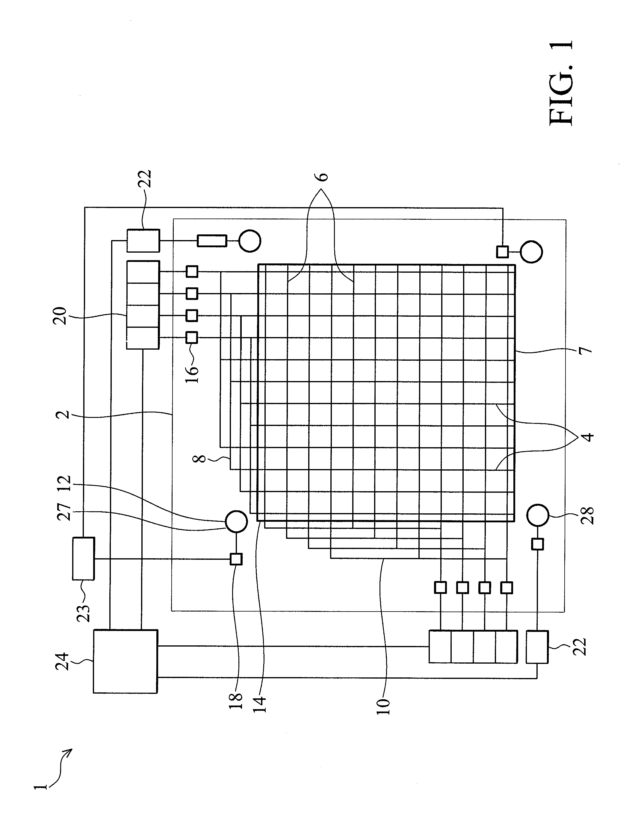
[0026]Referring to FIG. 1, a front position sensitive panel 1 for mounting at the front of a display is shown.

[0027]The panel 1 includes a transparent substrate 2, and a plurality of fine x-sense electrodes 4 arranged in parallel extending in a column direction across the substrate. A plurality of fine y-sense electrodes 6 extend in a row direction across the substrate, insulated from the fine x-sense electrodes. These cover a sensing region 7 of the panel, indicated ...


PUM


Abstract

A position sensing display integrates a touch sensor with an active matrix LCD panel. The panel includes both coarse and fine sensing means. The fine sensing means includes fine sense electrodes combined together in groups, the groups being interdigitated i.e. alternating across the display. In use, the fine sensing electrodes determine the position of a sensed object such as a stylus or finger accurately but non-uniquely, and the coarse sensing means determines which of the plurality of non-unique positions is correct.

Description

CROSS REFERENCE TO RELATED APPLICATIONS[0001]This application claims the benefit of U.S. Provisional Application No. 61 / 016,822, filed on Dec. 27, 2007, the entirety of which is incorporated by reference herein.[0002]This Application claims priority of European Patent Application No. 08163204.4, filed on Aug. 28, 2008, the entirety of which is incorporated by reference herein.BACKGROUND OF THE INVENTION[0003]1. Field of the Invention[0004]The invention relates to a position sensing display and a method of operation of such a display.[0005]2. Description of the Related Art[0006]Position sensors have been combined with displays in the form of a transparent position sensing overlay which is placed over the display to record touch or pen input. Such sensors may consist of arrays of electrodes which are connected to driving / sensing circuits.[0007]The sensors may be capacitance sensors with sets of electrodes connected to drive and / or sensing circuits. The location of an object such as a ...

Claims


Application Information

Patent Timeline
Patent Type & Authority Applications(United States)
IPC IPC(8): G06F3/041
CPCG06F3/044G06F3/0416G06F3/041661G06F3/0446
Inventor EDWARDS, MARTIN JOHN
Owner INNOLUX CORP
Learn More