Pneumatic tire
a technology of pneumatic tires and cylinders, which is applied in the direction of non-skid devices, vehicle components, transportation and packaging, etc., can solve the problems of incompressibility of rubber, blades may be bent or broken, etc., and achieve the reduction of narrowing of the openings of the sipes, easy bending, and increased ground contact performance
Inactive Publication Date: 2009-07-02
TOYO TIRE & RUBBER CO LTD
View PDF5 Cites 10 Cited by
- Summary
- Abstract
- Description
- Claims
- Application Information
AI Technical Summary
Benefits of technology
[0008]The present invention has been proposed in view of the above-described circumstances. An object of the present invention is to provide a pneumatic tire capable of reducing the narrowing of the openings of sipes and increasing ground-contact performance by ensuring the edge effect and the water removal effect thereby increasing on-ice braking performance while providing a satisfactory durability to a sipe-forming blade mounted on the tire manufacturing die.
[0010]According to the pneumatic tire of the present invention, the sipe is arranged so as to have the plurality of wide portions, which are arranged, in the sipe depth direction, alternately at the both sides of the sipe as viewed in the sipe width direction. Therefore, the tread rubber can be easily bent in the sipe depth direction. When a load is applied to the tire, the wide portions can absorb the deformation of the tread rubber due to the load. With this arrangement, the narrowing of the openings of the sipes is reduced. The edge effect and the water removal effect are ensured and the ground-contact performance is increased and thereby the on-ice braking performance is increased. Further, since the respective wide portions have their bottom portion, the rigidity of the land portion is prevented from decreasing too much.
[0011]The first sipe portion has a portion that is shared, in the depth direction, by the second sipe portion positioned at the bottom side of the first sipe portion. Likewise, the second sipe portion has a portion that is shared, in the depth direction, by the third sipe portion. That is, each of the sipe portions has a portion that, in the depth direction, is shared by the other neighboring sipe portion. On the other hand, with this arrangement, in the sipe forming blade also, the thick portions for forming the wide portions of the sipe have portions that are shared, in the depth direction, by the neighboring thick portions. As a result, the sipe-forming blade has no thin portions in the blade width direction. Therefore, the durability of the sipe-forming blade can be satisfactorily ensured.
[0012]On the other hand, according to the above-described structure, in the sipe, large cavity portions are formed corresponding to the wide portions. The rigidity of the land portion, which is formed with such sipes, tends to be reduced. However, the sipes are arranged so that the open-ends thereof, which are opened to the groove portions formed on the tread surface, have a shallower depth. With this arrangement, the rigidity of the land portion can be prevented from being reduced too much. As a result, this arrangement can preferably increase not only the on-ice braking performance but also the on-dry road braking performance (braking performance on dry road surface).
[0013]In the above arrangement, it is preferred that the ratio between the depth of the wide portion formed in the deepest portion as viewed in the depth direction and the depth in the other wide portions is arranged to be 1.1 to 2. Ordinarily, when the tire wears and the height of the land portion decreases, the rigidity of the land portion increases from a middle stage to a final stage of the wear. However, the sipes are arranged so that the depth of the wide portion, which is formed in the deepest portion of the sipe as viewed in the depth direction, to be larger than the depth of other wide portions. Therefore, even after the middle stage of the wear, the rigidity of the land portion is reduced and the land portion can be easily bent. As a result, even after the middle stage of the wear, the yielding of the land portion can be ensured. Therefore, the on-ice braking performance and the like can be satisfactorily obtained.
Problems solved by technology
Generally, rubbers have incompressibility.
As a result, the blade may be bent or broken.
Method used
View moreImage
Smart ImageViewing Examples

Examples
example
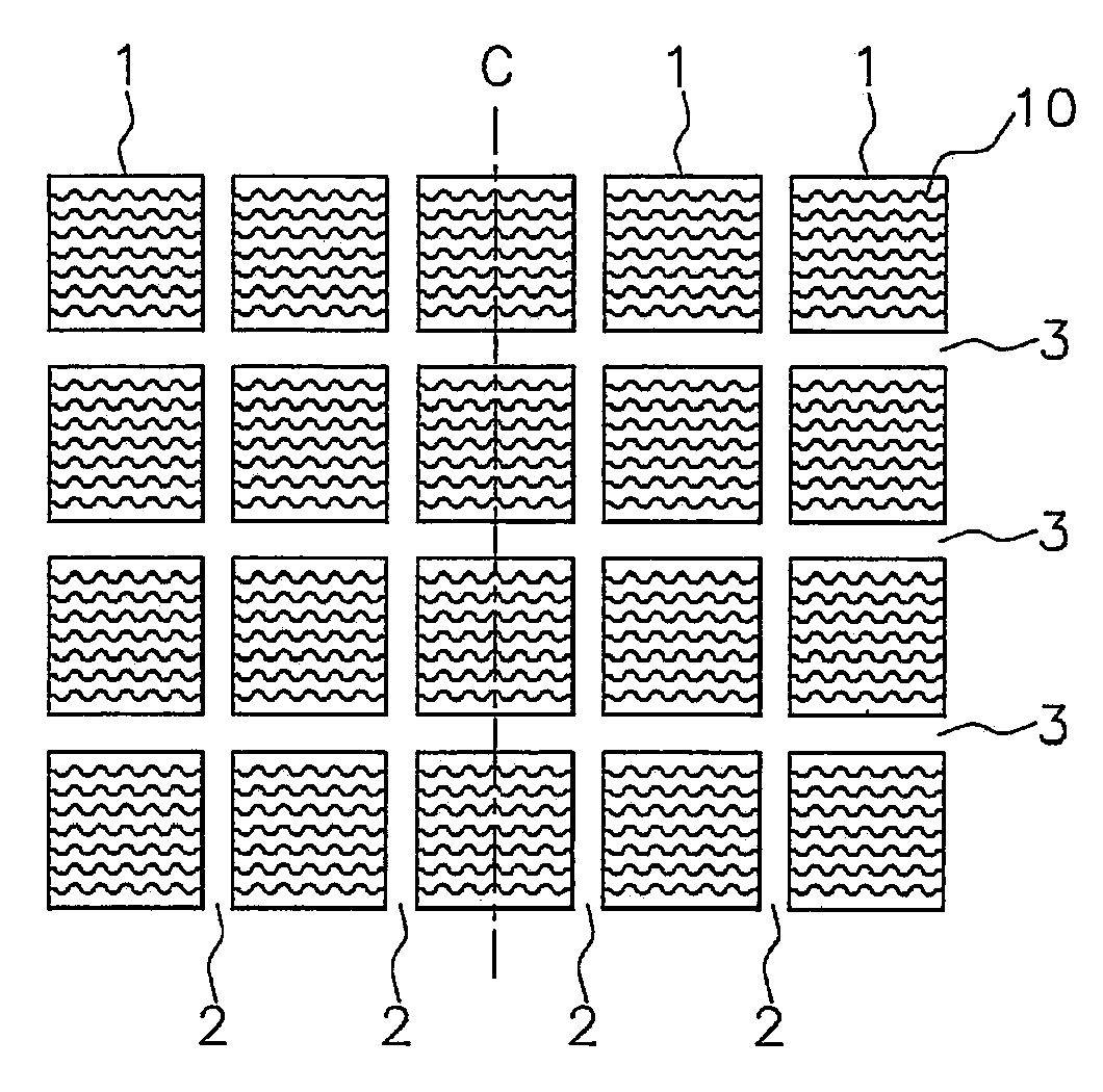
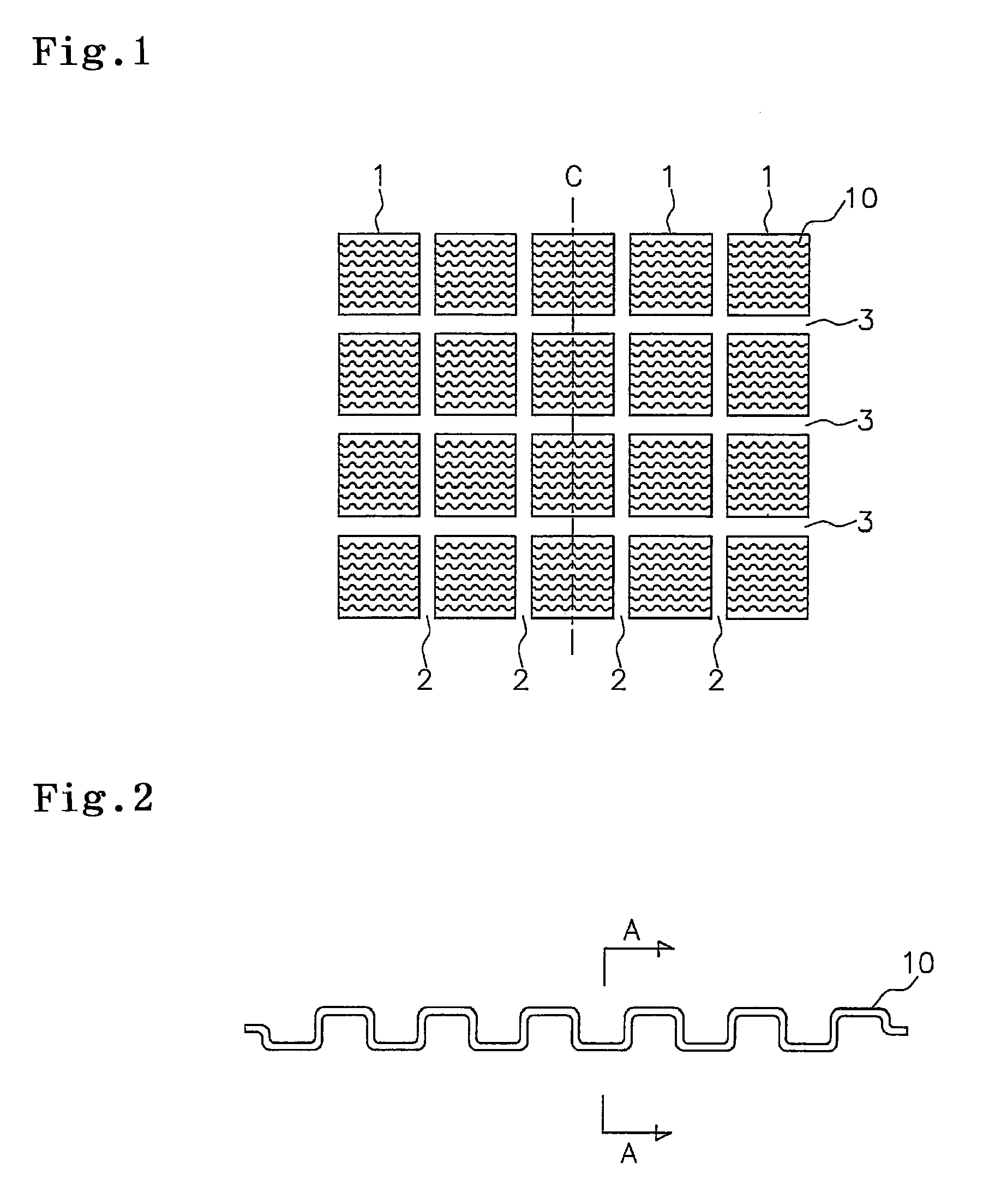
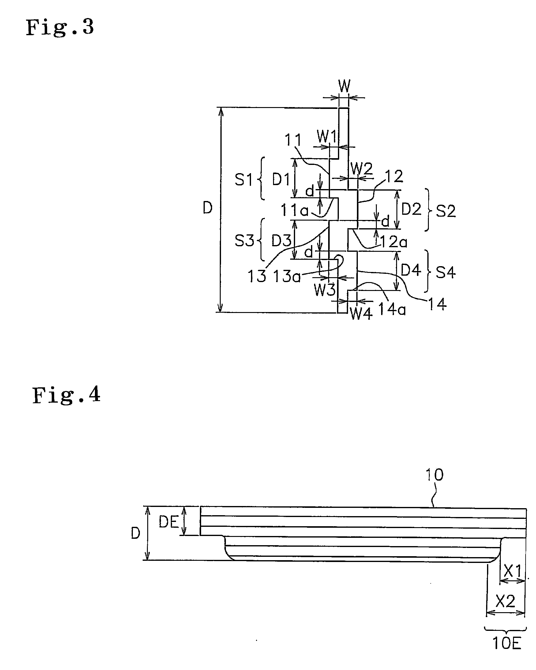
[0042]In a pneumatic tire (tire size 205 / 65R15) formed with wave sipes shown in FIGS. 2 to 4, the respective values of the wave sipes were set up as below; i.e., W=0.3, D=6.5, DE=3, d=0.3, D1=D2=D3=1.3, D4=1.5, W1=W2=W3=W4=0.3, X1=2 and X2=3.
Login to View More PUM
 Abstract
An object of the present invention is to provide a pneumatic tire capable of reducing the narrowing of the openings of sipes and increasing ground-contact performance by ensuring the edge effect and the water removal effect thereby increasing on-ice braking performance while providing a satisfactory durability to a sipe-forming blade mounted on the tire manufacturing die. To achieve the above object, each of the sipes formed in a land portion of a tread surface which a pneumatic tire comprises has: a first sipe portion in which a first wide portion having a bottom portion thereof is formed, a second sipe portion in which a second wide portion having a bottom portion thereof and extending in a depth direction from a depth position closer to the tread surface side than the bottom portion of the first wide portion is formed at the side opposite to the first wide portion as viewed in a sipe width direction, the second sipe portion being positioned on the side of the bottom portion of the first sipe portion, and a third sipe portion in which a third wide portion having a bottom portion thereof and extending in a depth direction from a depth position closer to the tread surface side than the bottom portion of the second wide portion is formed at the same side as the first wide portion as viewed in a sipe width direction, the third sipe portion being positioned on the side of the bottom portion of the second sipe portion.
Description
BACKGROUND OF THE INVENTION[0001]1. Field of the Invention[0002]The present invention relates to a pneumatic tire, comprising a tread surface including a land portion in which a plurality of sipes are formed. The pneumatic tire is particularly useful as a studless tire.[0003]2. Description of the Related Art[0004]Conventionally, in studless tires, a land portion such as a block, a rib and the like is formed with cuts called sipes. With edge effect and water removal effect that are obtained with the sipes, the driving performance of a vehicle is enhanced on snow-covered / iced load surfaces having small friction coefficient. As such sipes, a straight sipe extending linearly in a length direction of the sipe, a wave sipe extending in a wave-like configuration and the like have been put into actual use.[0005]Generally, rubbers have incompressibility. Therefore when a load is applied to a tire, a tread surface thereof coming into contact with a road surface deforms largely causing the ope...
Claims
Login to View More Application Information
Patent Timeline
 IPC IPC(8): B60C11/13
CPCB60C11/1281B60C11/12B60C11/1263B60C11/1218
Inventor OHASHI, TOSHIYUKI
Owner TOYO TIRE & RUBBER CO LTD
Features
- R&D
- Intellectual Property
- Life Sciences
- Materials
- Tech Scout
- Unparalleled Data Quality
- Higher Quality Content
- 60% Fewer Hallucinations
Learn More Browse by: Latest US Patents, China's latest patents, Technical Efficacy Thesaurus, Application Domain, Technology Topic, Popular Technical Reports.
© 2025 PatSnap. All rights reserved.Legal|Privacy policy|Modern Slavery Act Transparency Statement|Sitemap|About US| Contact US: help@patsnap.com