
Apparatus and method for drying a solid or liquid sample

a technology of apparatus and liquid sample, which is applied in the direction of separation process, centrifuge, furnace, etc., can solve the problems of high-performance systems working with water-containing solvents, time-consuming and expensive multi-step compound processing, and high cost of vacuum systems to buy and operate. , to achieve the effect of high blowing gas velocity

Inactive Publication Date: 2009-07-02
BANK OF AMERICA N A
View PDF16 Cites 17 Cited by
  • Summary
  • Abstract
  • Description
  • Claims
  • Application Information

AI Technical Summary

Benefits of technology

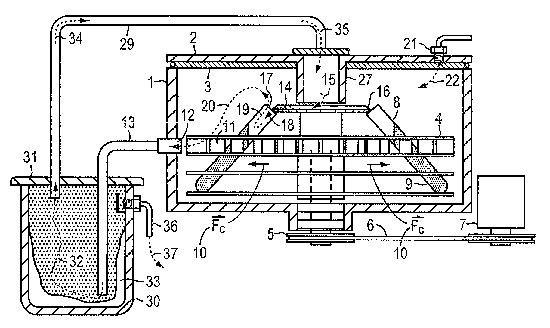
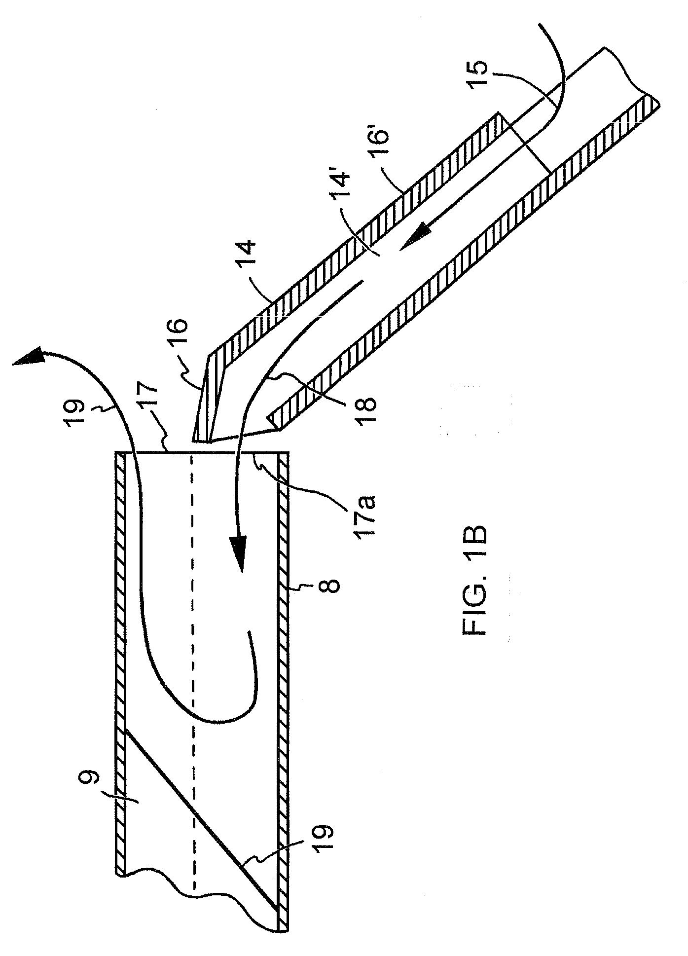
[0011]In this embodiment, the centrifugal force holds the sample intact in the tube container. The present invention allows a substantially higher velocity of blow down gas to the driven into the tube container. The effect is that the drying rate for the sample without the use of a vacuum may be five or more times higher than in known blow down driers. In addition, the centrifugal force maintains sample integrity to allow the present invention to dry the sample completely to a dry fine particulate powder.

Problems solved by technology

Multi-step compound processing is time consuming and expensive, and drying steps are in the critical path of any process because drying must be complete before the next step begins.
High performance vacuum systems are needed to speed drying, but such vacuum systems are expensive to buy and operate.
However, these expensive, high performance systems working with water-containing solvent (which is the most commonly occurring solvent in biological samples) still only have the ability to remove water at about 0.5 mL / hr.
This approach retains the expensive vacuum system while adding, in some applications, expensive refrigeration equipment.
If water is used as a solvent, the time to pre-freeze compound solutions adds to the time and effort to bring the compounds to dryness.
Blow down concentrators are not recommended for complete drying since the flow of drying gas will carry away the dry material.
Furthermore, it is suggested that the solution not be dried to a powder, but to a more concentrated liquid state, since this conservative gas flow rate may disturb a dry sample.
The inability to dry completely a sample solution reduces the performance of blow down concentrators, and their consumption of gas (usually nitrogen) adds to the operating costs of blow down systems.

Method used


Image

  • Apparatus and method for drying a solid or liquid sample
  • Apparatus and method for drying a solid or liquid sample
  • Apparatus and method for drying a solid or liquid sample

Examples


Embodiment Construction

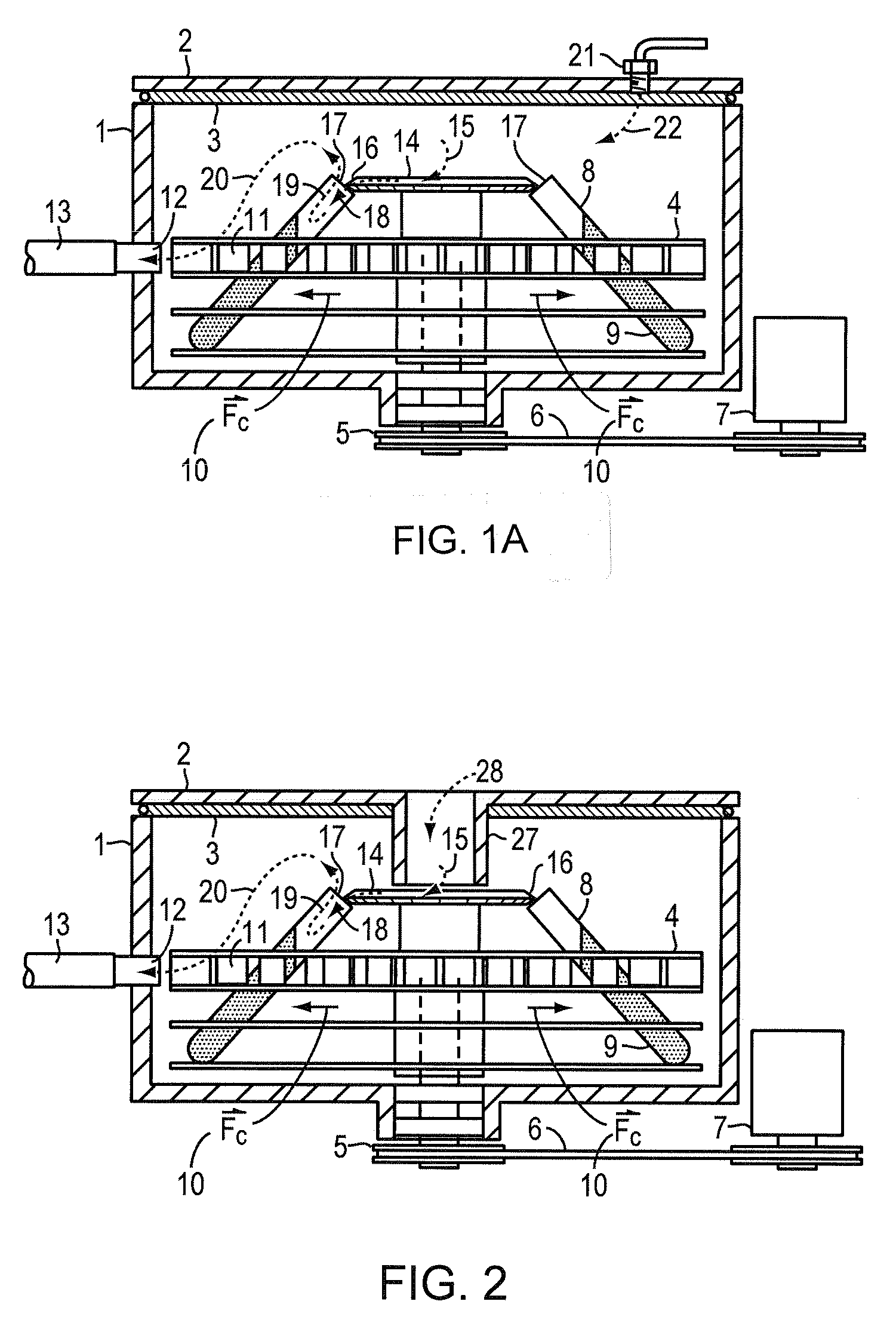
[0024]FIG. 1A shows a cross section of a typical centrifugal vacuum concentrator where a spinning carrier 4 is contained within a closed environment comprising an enclosure housing 1 and a cover 2 between which is fitted a gasket 3 to prevent solvent vapors from escaping into the user workspace. Carrier 4 is rotated at moderate speed, for example 1,500 RPM, by spindle, bearing, and pulley assembly 5 driven by V-belt 6 which is powered by motor pulley assembly 7.

[0025]Collection tube containers 8 are filled with the mixture 9 to be dried and inserted into sample carrier 4. The centrifugal force generated by the spinning sample carrier 4 holds the sample material 9 within the tube containers. This force maintains sample integrity in fraction collector applications by maximizing the capture rate of non volatile sample materials. In this drying application the yield and purity of non-volatile sample materials is preserved by the centrifugal force despite the relatively violent flow of a...


PUM

PropertyMeasurementUnit
Flow rateaaaaaaaaaa
Volumeaaaaaaaaaa
Speedaaaaaaaaaa

Abstract

This disclosure describes a sample drying system and method that provides a high rates of evaporation and sublimation that is commonly employed in compound processing procedures. The drying increases the sample-solute concentration and removes the solvent completely to produce the dried sample as a non-volatile solute precipitate. Re-circulating of drying gas is disclosed along with a solvent cold trap.

Description

RELATED APPLICATIONS[0001]The present application claims the benefit and priority of the following commonly owned U.S. patent applications. A.) Centrifugal Fraction Collection System and Method, filed Sep. 19, 2007, Ser. No. 11 / 901,817. B.) U.S. Provisional Patent Applications, all entitled “Device and Method for Concentration of Solvents,” application Nos. 61 / 009,816, filed Jan. 2, 2008; 61 / 010,435, filed Jan. 8, 2008; and 61 / 010,670, filed Jan. 10, 2008, respectively. These applications are hereby incorporated herein by reference.BACKGROUND OF THE INVENTION[0002]1. Field of the Invention[0003]The present invention relates to the removal of solvents from a solution to produce non-volatile material or precipitates, and more particularly to provide high rates of evaporation and sublimation commonly applied in compound processing procedures to accelerate production of dry non-volatile materials.[0004]2. Background Information[0005]Compound processing to separate mixtures of chemical c...

Claims


Application Information

Patent Timeline
IPC IPC(8): F26B5/08F26B17/30F26B7/00F26B21/04
CPCB01D1/14B01D3/346B04B5/0414B04B15/08G01N2001/4027F26B21/006F26B25/006G01N1/4022F26B5/08
Inventor HEDBERG, HERBERT J.KANGAS, BRIAN
Owner BANK OF AMERICA N A
Learn More