Ultrasonic dental insert and lighted handpiece assembly

Inactive Publication Date: 2009-06-25
WERNER PETER +2
View PDF6 Cites 29 Cited by
  • Summary
  • Abstract
  • Description
  • Claims
  • Application Information

AI Technical Summary

Problems solved by technology

This causes the tip of the insert to vibrate.
However, there is no disclosure of a flexible light guide that can bend and flex in any direction.

Method used


Image

  • Ultrasonic dental insert and lighted handpiece assembly
  • Ultrasonic dental insert and lighted handpiece assembly
  • Ultrasonic dental insert and lighted handpiece assembly

Examples


Embodiment Construction

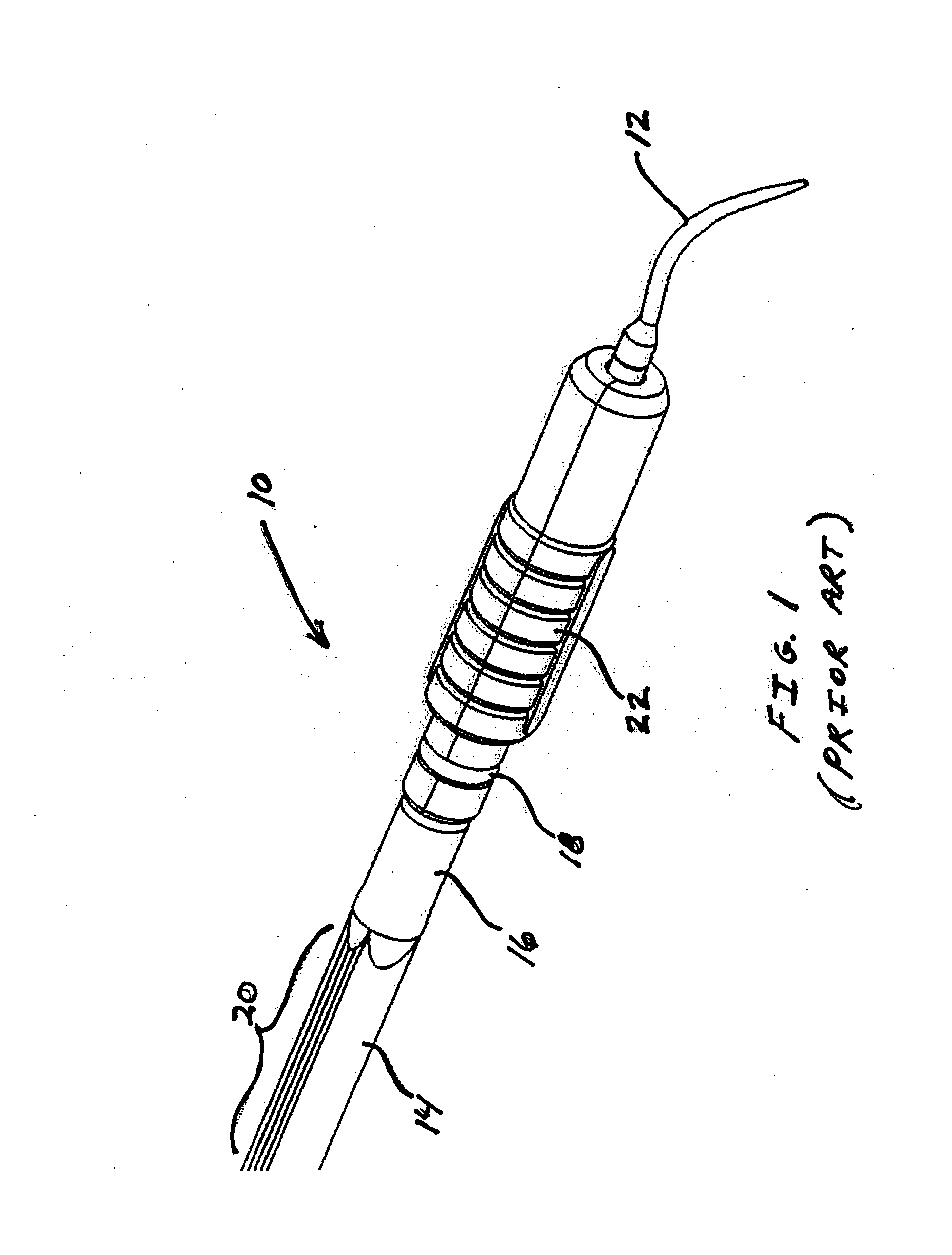
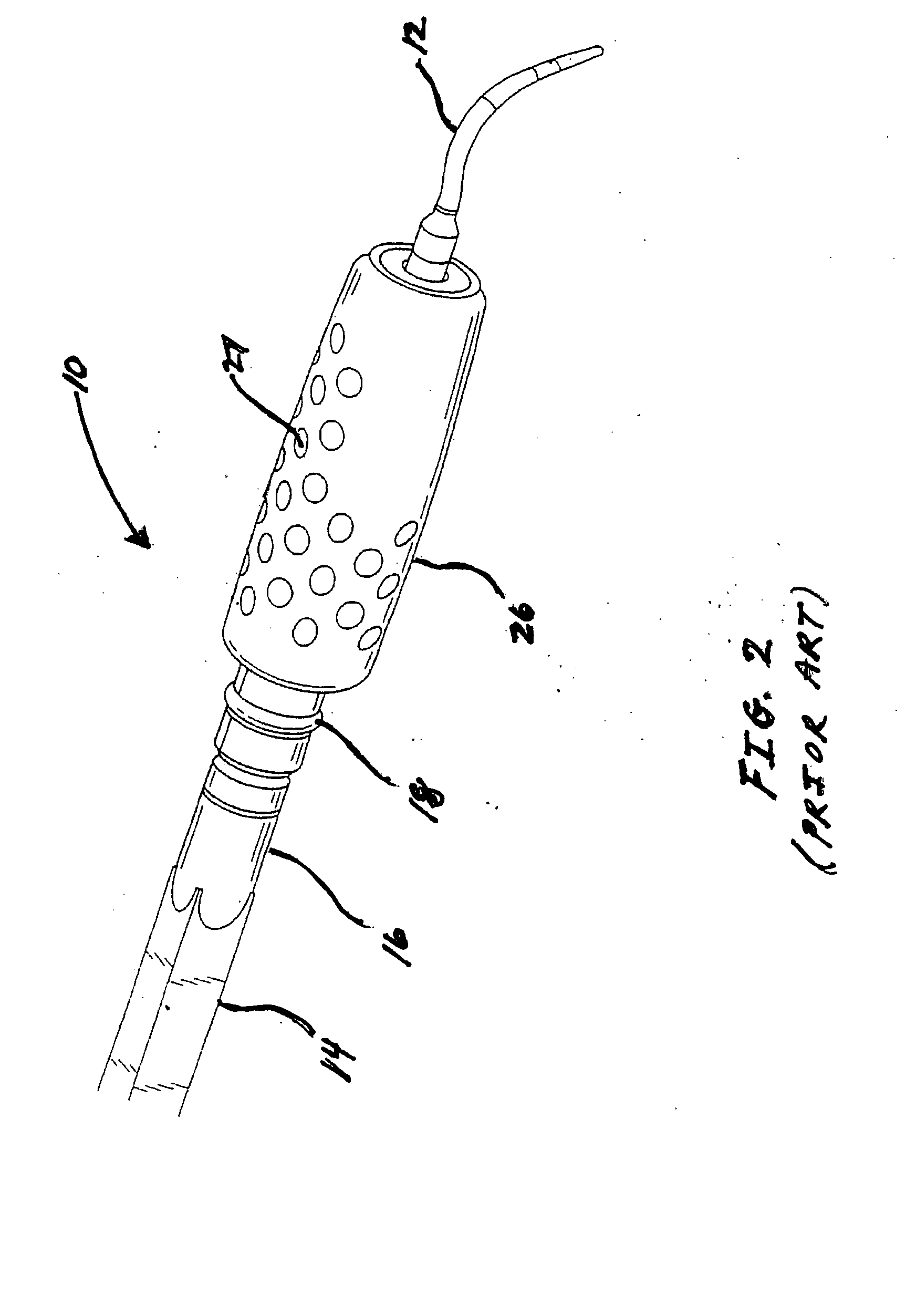
[0022]Referring to FIG. 1, one embodiment of a dental insert that can be used in the assembly of the instant invention is shown and generally indicated at (10). Although the dental insert (10) is described herein primarily as being an ultrasonic scaling insert, it should be understood that this is for illustration purposes and other dental inserts can be used in the assembly of this invention as needed. For example, air polishing inserts, endodontic inserts, and drills can be used. The insert (10) can be designed to deliver air, powder, water, and other fluids as is known in the art.

[0023]Ultrasonic scaling inserts are commonly known in the dental field and can be used in accordance with this invention, provided that they are compatible with the dental handpiece. For example, Cavitron® Focused Spray® Slimline® ultrasonic insert, available from Dentsply International, can be used in the handpiece assembly. In general, the scaling insert (10) includes a tip (12) located at a first end...


PUM


Abstract

An ultrasonic dental handpiece and insert assembly is provided. Scaler inserts that can be used to clean and polish tooth surfaces are particularly preferred. A sleeve is removably mounted on the handpiece. The handpiece contains a primary coil and the sleeve encloses a secondary coil, which are inductively coupled together so that electromagnetic energy can be transferred between them. A flexible light guide member having a light source such as a light-emitting diode extends from the sleeve. The light guide can bend and flex in any direction allowing the light source to emit light in any direction.

Description

BACKGROUND OF THE INVENTION[0001]1. Field of the Invention[0002]The present invention relates generally to dental instruments that can be used for cleaning and polishing teeth. More particularly, the invention relates to dental inserts installed in ultrasonic dental handpieces. Scaling and polishing inserts are some examples of inserts that can be used. The handpiece includes a removable sleeve with a light source for illuminating the working area inside of the mouth. The light source is coupled to a flexible light guide.[0003]2. Brief Description of the Related Art[0004]Dental practitioners commonly use dental handpieces equipped with ultrasonic scaling inserts for providing therapeutic and preventive care to their patients. For example, Steri-Mate® handpieces (Dentsply) can be equipped with ultrasonic inserts to remove calculus deposits and heavy plaque from tooth surfaces. Ultrasonic scaling also may be used for periodontal debridement in treating periodontal diseases.[0005]Conve...

Claims


Application Information

Patent Timeline
IPC IPC(8): A61C1/07
CPCA61C17/20A61C1/088
Inventor WERNER, PETERCHRONISTER, BENJAMINBARTO, MATT
Owner WERNER PETER
Why Eureka
Try Eureka