Efficiency-modulated ultrasonic instrument inserts

a technology of efficiency modulation and inserts, which is applied in the field of ultrasonic instrument inserts, can solve the problems of metal fatigue, tip breakage, and inability to operate correctly, and achieve the effects of avoiding overpowering the tip, reducing fatigue, and reducing fatigu

Inactive Publication Date: 2013-11-19
FEINE JAMES S
View PDF8 Cites 2 Cited by
  • Summary
  • Abstract
  • Description
  • Claims
  • Application Information

AI Technical Summary

Benefits of technology

[0010]This invention allows the manufacturer to custom design or adjust the power range of the tip / stack assembly (insert) to match the power range of the power output range of the ultrasonic generator. This allows the full range control of the generator to be used regardless of the tip thickness and / or shape while automatically modulating the power converted to the handpiece / insert when power-sensitive tips are employed to prevent overpowering independently of any operator-adjustable power control. The present invention enables the manufacturer of magnetostrictive ultrasonic dental inserts to design the stack system, usually nickel vibrating elements, to be efficiency modulated to match the operating characteristics of power-sensitive tips.
[0011]Generally, the power conversion by the magnetostrictive element is proportional to the amount of magnetostrictive material in the handpiece insert at the peak resonant frequency. The efficiency-modulated magnetostrictive element with specific energy conversion efficiency can be power matched to a power sensitive tip operable in a specific power range of a specific power supply. Thus, operators can use the full range of power adjustment setting of their ultrasonic dental generator as they are accustomed to using with the generally thicker, less sensitive tips, without overstressing the thinner tip and causing premature metal fatigue tip breakage, or otherwise overpowering a power-sensitive tip. Each type or style of tip and frequency used, commonly 25 KHz, 30 KHz or another frequency, can be manufactured with the appropriate efficiency-modulated stack to enable the operator to achieve the full operating life of the insert without inadvertent metal fatigue tip breakage.

Problems solved by technology

If a tip is connected to an insert and used with a generator and handpiece that operate at the improper frequency or power output, the tip may not operate correctly, or can break during operation.
Unless modulated in some manner, usually by manually adjusting a power setting control such as a knob connected to a potentiometer, the ultrasonic power required to vibrate the thicker tips can overstress the thinner tips, creating metal fatigue and causing tip breakage, sometimes within a matter of seconds.
Other special-use tips may vibrate excessively at the typical maximum ultrasonic power levels, making them difficult for the dental practitioner to use, and / or causing patient discomfort.
At some point, however, the power input will become excessive in that a sharp increase from the normally linear stress-strain curve for the material of the tip will occur, resulting in accelerated failure of the tip, and / or in that the tip becomes difficult to use or begins to cause patient discomfort.
This has been only partially effective due to operator error, for example the operator may not remember to reduce the power setting before use, as well as complications due to the variations in the numerous makes and models of many manufacturers and the differences in the circuitry of their ultrasonic dental generators.
The device is generally unconcerned with protection of power-sensitive tips, as the efficiency of the magnetostrictive element is optimized independent of the tip used.
Generally, there is no method, other than reducing power output of the power supply, e.g. with a manually adjusted potentiometer, to prevent metal fatigue, tip breakage, operational difficulty, patient discomfort, or the like occurring due to tip power-sensitivity.
The reduced magnitude of oscillation of the tip is unrelated to tip sensitivity and, therefore does not provide a method of automatically preventing overpowering power-sensitive tips and the concomitant metal fatigue, tip breakage, operational difficulty, or patient discomfort.

Method used


Image

  • Efficiency-modulated ultrasonic instrument inserts
  • Efficiency-modulated ultrasonic instrument inserts
  • Efficiency-modulated ultrasonic instrument inserts

Examples


Embodiment Construction

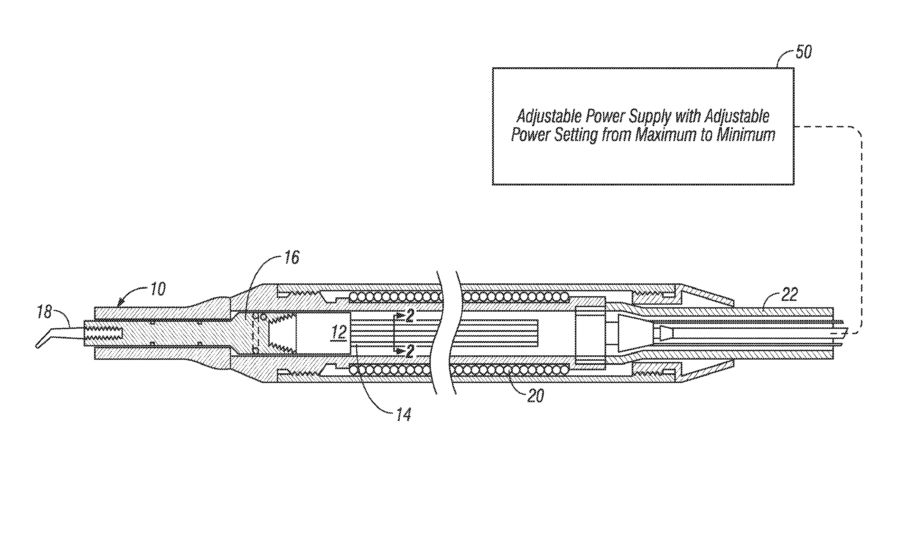
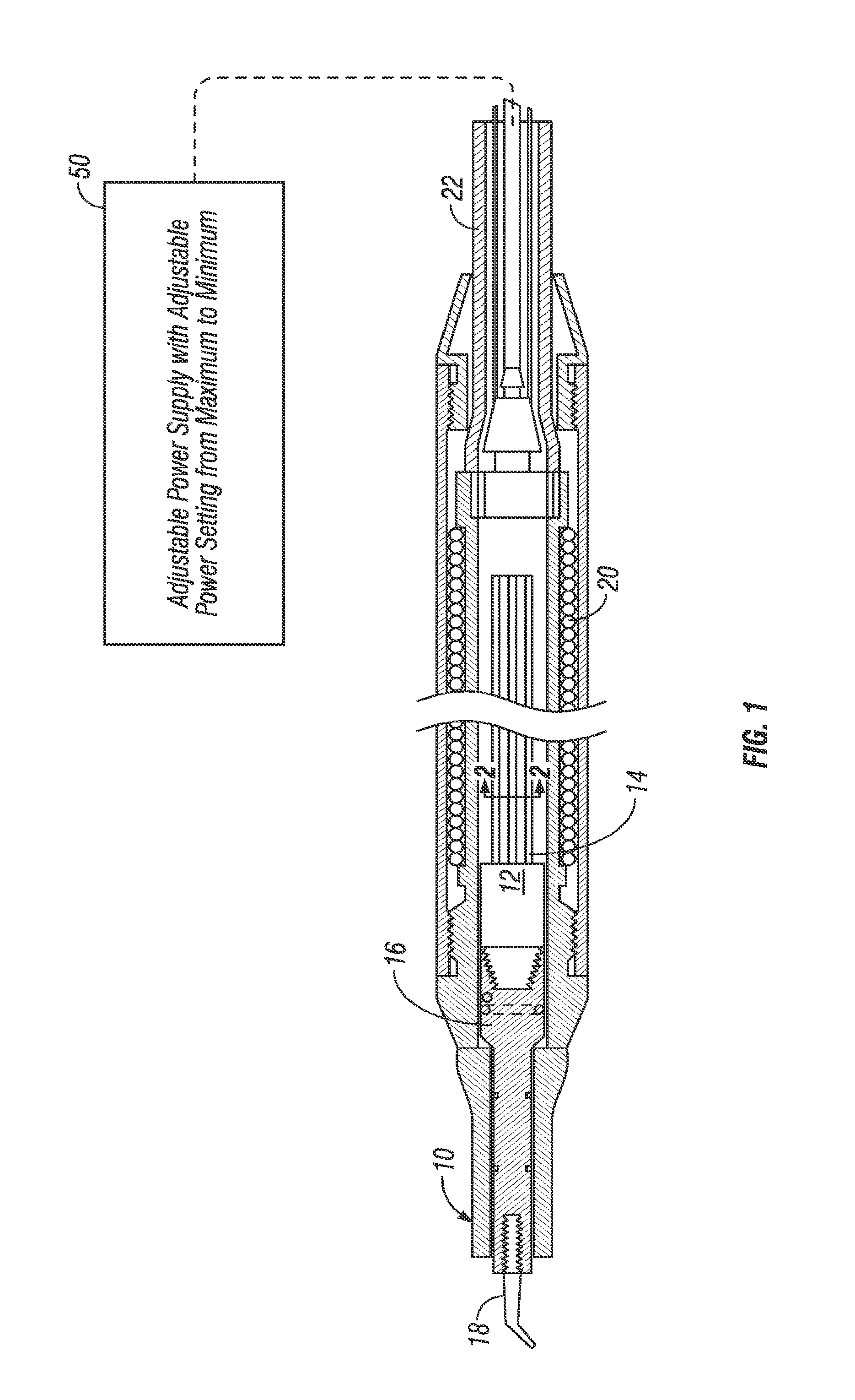
[0038]With reference to the figures wherein like reference numerals are used to refer to like parts, FIG. 1 shows the handpiece 10 receiving the insert 12 in a well known manner, e.g. by a friction fitting, which can generally be considered conventional in the art. The insert 12 includes a magnetostrictive element 14, velocity transducer 16 and power-sensitive tip 18. Briefly, the handpiece 10 has a well for receiving the insert 12 about which an inductive coil 20 is disposed for imposing an alternating magnetic field that oscillates the magnetostrictive element 14 at an ultrasonic frequency. The ultrasonic vibrations are transmitted from the magnetostrictive element 14 through the velocity transducer 16 and the tip 18, as is well known in the art. Electrical current from a power supply and control unit (not shown) is conventionally supplied to a proximal end of the handpiece 10 via the cable assembly 22.

[0039]Water is also supplied via the cable assembly 22 and cools the magnetostr...


PUM


Abstract

Efficiency-modulated ultrasonic dental inserts (12) are disclosed for preventing the overpowering of power-sensitive tips (18). The inserts (12) are useful in a handpiece (10) having an induction coil (20) disposed about a well and operable with an adjustable power supply having a maximum power output setting. An efficiency-modulated magnetostrictive element (14) is adapted to be received in the well. A velocity transducer (16) has proximal and distal ends. The proximal end is attached to a distal end of the magnetostrictive element (14). A power-sensitive tip (18) has a proximal end secured to the distal end of the velocity transducer (16). The efficiency of the magnetostrictive element (14) is matched with the power range of the tip (18) to prevent overpowering the tip (18) at the maximum power output setting.

Description

CROSS REFERENCE TO RELATED APPLICATIONS[0001]This application is a divisional application of my earlier U.S. Ser. No. 11 / 161,743 filed Aug. 15, 2005, abandoned, which is a continuation-in-part U.S. Ser. No. 10 / 065,991 filed Dec. 7, 2002, abandoned, and claims the benefit of provisional application U.S. Ser. No. 60 / 340,575 filed Dec. 7, 2001.BACKGROUND OF INVENTION[0002]This invention relates to ultrasonic instrument inserts, more particularly, to magnetostrictive inserts for ultrasonic dental instruments, and especially to such inserts that are power-matched to the power range of a power-sensitive tip.[0003]Ultrasonic instruments such as dental scalers are well known. The ultrasonic scalers include a generator that electrically induces the scaling tip to vibrate at a very high rate. An alternating current is passed through an induction coil in a handpiece that induces vibration of the magnetostrictive element of an insert in the handpiece. The vibration is transmitted to the tip by ...

Claims


Application Information

Patent Timeline
Patent Type & Authority Patents(United States)
IPC IPC(8): A61C1/07
CPCA61C17/20
Inventor FEINE, JAMES S.
Owner FEINE JAMES S
Why Eureka
Try Eureka