
Resin-Sealing and Molding Apparatus with Sealing Mechanism and Method of dismounting Contitiuent Part of Die Assembly Fitted Therein

a technology of sealing mechanism and die assembly, which is applied in the direction of metal working apparatus, butter manufacturing, manufacturing tools, etc., can solve the problems of air bubble formation in the resin sealing process, and achieve the effect of preventing the reduction of air tightness in the internal space and not reducing the efficiency of operation

Inactive Publication Date: 2009-06-25
TOWA
View PDF3 Cites 8 Cited by
  • Summary
  • Abstract
  • Description
  • Claims
  • Application Information

AI Technical Summary

Benefits of technology

[0027]According to the present invention, a resin-sealing and molding apparatus having sealing mechanism capable of preventing reduction of airtightness in the internal space of a die assembly without reducing the efficiency of an operation for exchanging the die assembly and a method of dismounting a constituent part of the die assembly fitted in this apparatus can be provided.

Problems solved by technology

Consequently, voids (air bubbles) are formed in the resin-sealing and molding and on the surface thereof.

Method used


Image

  • Resin-Sealing and Molding Apparatus with Sealing Mechanism and Method of dismounting Contitiuent Part of Die Assembly Fitted Therein
  • Resin-Sealing and Molding Apparatus with Sealing Mechanism and Method of dismounting Contitiuent Part of Die Assembly Fitted Therein
  • Resin-Sealing and Molding Apparatus with Sealing Mechanism and Method of dismounting Contitiuent Part of Die Assembly Fitted Therein

Examples


Embodiment Construction

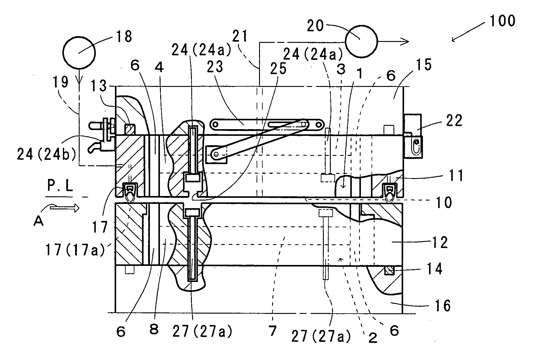
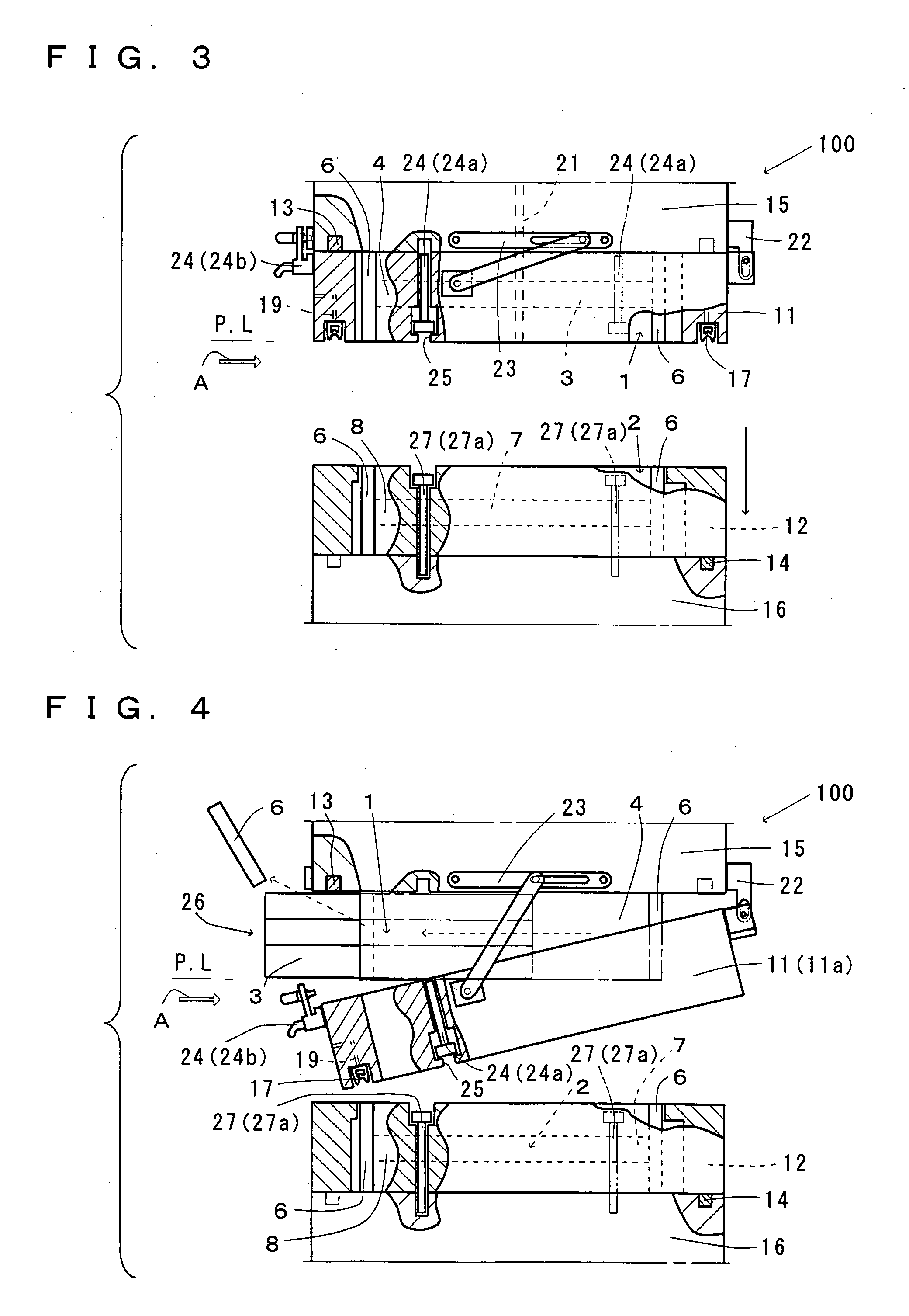
[0038]A resin-sealing and molding apparatus according to an embodiment is now described with reference to FIGS. 1 to 8. Front elevational views included in FIGS. 1 to 8 illustrate the apparatus as viewed along the direction of a path for exchanging a die assembly. Therefore, the forward end of arrow A in the figures denotes a specific plane in the path for extracting and dismounting the die assembly, and this plane is referred to as an exchange plane A.

[0039]As shown in FIGS. 1 to 8, a resin-sealing and molding apparatus 100 (hereinafter simply referred to as “apparatus 100”) according to this embodiment comprises a die assembly. The die assembly has an upper die 1 whose position is fixed and a movable lower die 2 opposed to upper die 1.

[0040]Apparatus 100 comprises a basement (not shown) and a necessary number of tie-bars 50 vertically extending from the basement, as shown in FIGS. 2 and 5 to 8. A fixed member (not shown) is fixed to the upper end of each tie-bar 50. A movable memb...


PUM

PropertyMeasurementUnit
vacuumaaaaaaaaaa
degree of vacuumaaaaaaaaaa
moldingaaaaaaaaaa

Abstract

A resin-sealed molding apparatus furnished with sealing means. The sealing means includes upper-die-side ambient air shutoff member fixed to upper-die-side mount base board so as to surround the lateral side of upper die and lower-die-side ambient air shutoff member fixed to lower-die-side mount base board so as to surround the lateral side of lower die. The upper-die-side ambient air shutoff member is fixed to the upper-die-side mount base board by means of upper-die-side fixing tool. The lower-die-side ambient air shutoff member is fixed to the lower-die-side mount base board by means of lower-die-side fixing tool. The upper-die-side ambient air shutoff member and the upper-die-side mount base board are rotatably connected by means of axis member. Only by dismounting of the lower-die-side fixing tool from the lower-die-side mount base board and the lower-die-side ambient air shutoff member, there can be realized the state in which the lower-die-side ambient air shutoff member can be completely dismounted from the lower-die-side mount base board.

Description

TECHNICAL FIELD[0001]The present invention relates to an improvement of sealing mechanism provided on an apparatus sealing and molding an electronic component such as an IC (Integration Circuit) with a die assembly and a method of dismounting a constituent part of the die assembly fitted in this apparatus.BACKGROUND ART[0002]A resin-sealing and molding apparatus (hereinafter simply referred to as “apparatus” as well) furnished with a die assembly having an upper die and a lower die is employed in general. In this apparatus, air containing moisture such as the so-called damp remains in the internal space of the die assembly. In resin-sealing and molding, therefore, the residual air is mixed into a melted resin material. Consequently, voids (air bubbles) are formed in the resin-sealing and molding and on the surface thereof.[0003]A sealing mechanism and a decompression mechanism are provided in order to prevent the aforementioned formation of voids. The sealing mechanism is employed f...

Claims


Application Information

Patent Timeline
Patent Type & Authority Applications(United States)
IPC IPC(8): B29C33/30B23P19/00
CPCB29C45/2608H01L21/565Y10T29/49815H01L2924/0002H01L2924/00B29C45/14B29C45/17H01L21/56
Inventor IJIRI, KAZUHIRO
Owner TOWA
Learn More