
Display device, video signal correction device, and video signal correction method

a technology of video signal and display panel, which is applied in the direction of color signal processing circuits, instruments, television systems, etc., can solve the problems of increasing system cost and difficulty in speed enhancement, affecting the uniformity of display panel luminance and chromaticity, and limited flexibility in setting representative input values. , to achieve the effect of improving the uniformity of display panel, and reducing the difficulty of hardware implementation

Inactive Publication Date: 2009-06-25
SONY CORP
View PDF2 Cites 3 Cited by
  • Summary
  • Abstract
  • Description
  • Claims
  • Application Information

AI Technical Summary

Benefits of technology

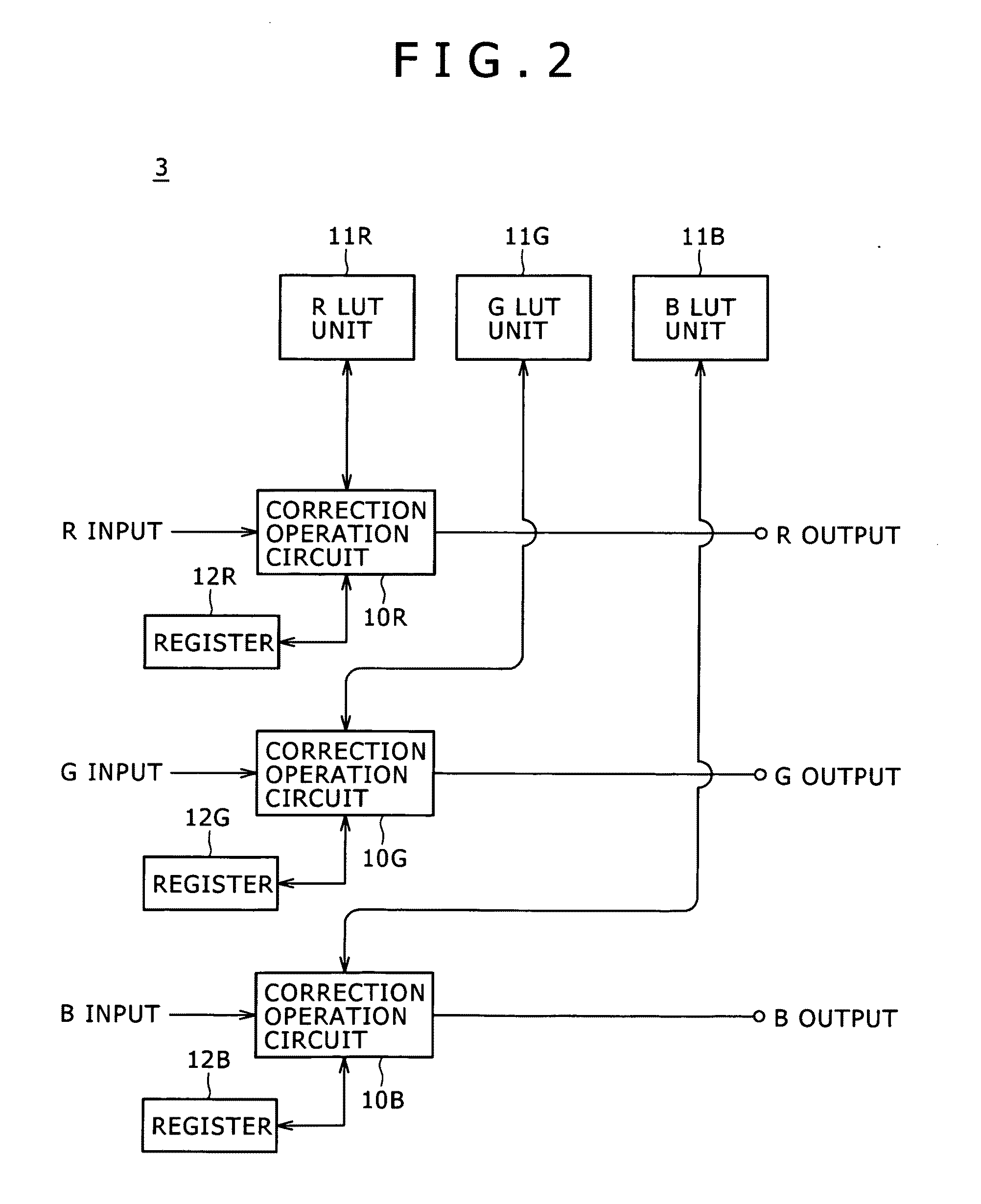
The present invention relates to a video signal correction device and method for improving the uniformity of a display panel. The device includes a memory table unit and a correction operation unit that reads operation results from reference tables in advance and performs arithmetic operations to calculate a corrected video signal value. The device can flexibly set the representative input values and can be used as a 3D-γ system. The technical effects of the invention include the ability to correct luminance unevenness and chromaticity unevenness without the need for a divider, increased flexibility in setting the representative input values, and improved uniformity of the display panel.

Problems solved by technology

Although the configuration of FIG. 12 includes the divider 116, it is generally difficult to implement the divider by hardware, and the provision of the divider involves problems of increase in the system cost and difficulty in speed enhancement.
However, in this case, the interval of the sampling of the representative input values along the Z axis (grayscale value) direction needs to be set to a power of two, and therefore the flexibility of the setting of the representative input values is limited.
However, it is impossible to realize such setting with use of only the shift operation unit.

Method used


Image

  • Display device, video signal correction device, and video signal correction method
  • Display device, video signal correction device, and video signal correction method
  • Display device, video signal correction device, and video signal correction method

Examples


Embodiment Construction

[0065]An embodiment of the present invention will be described below.

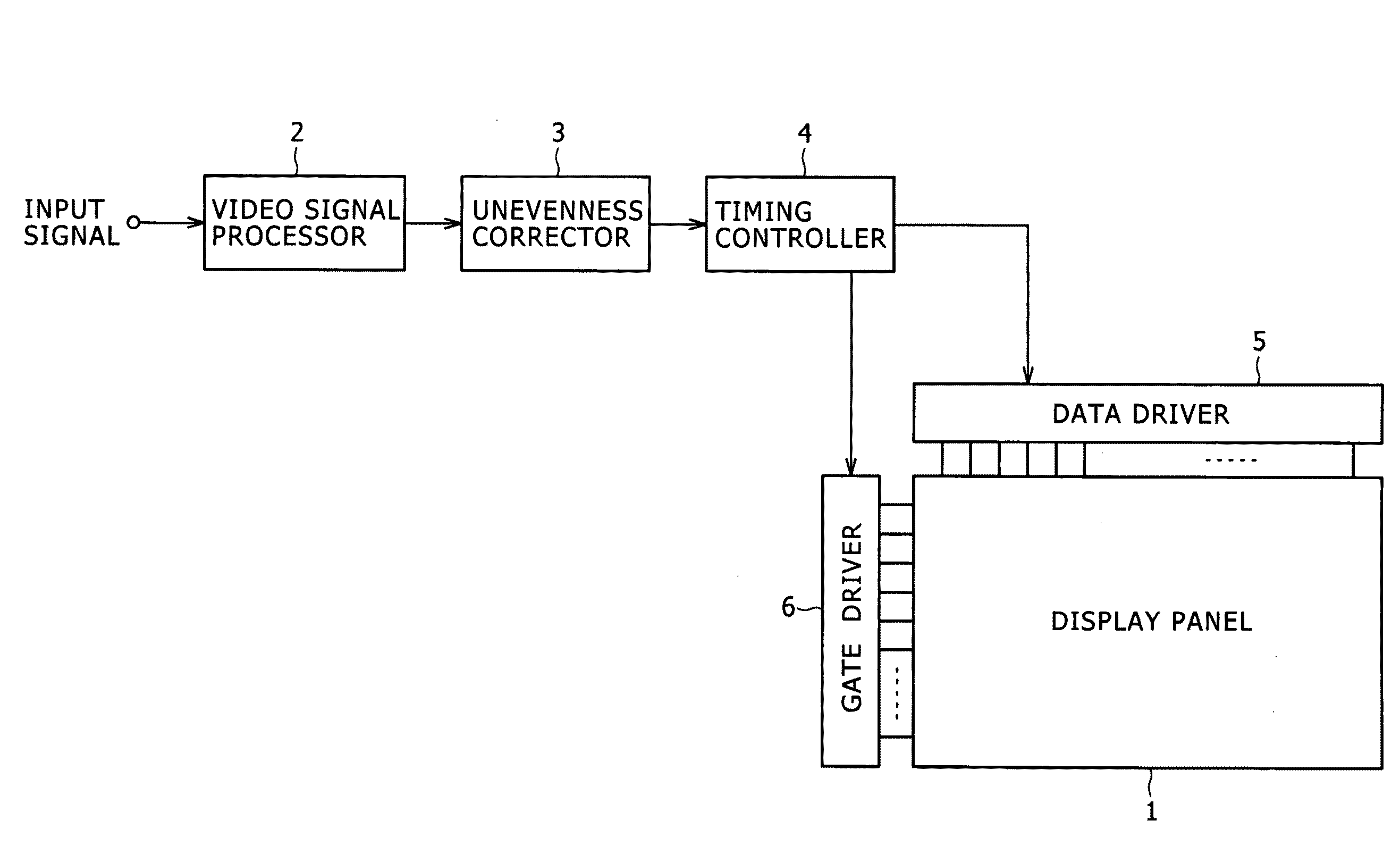
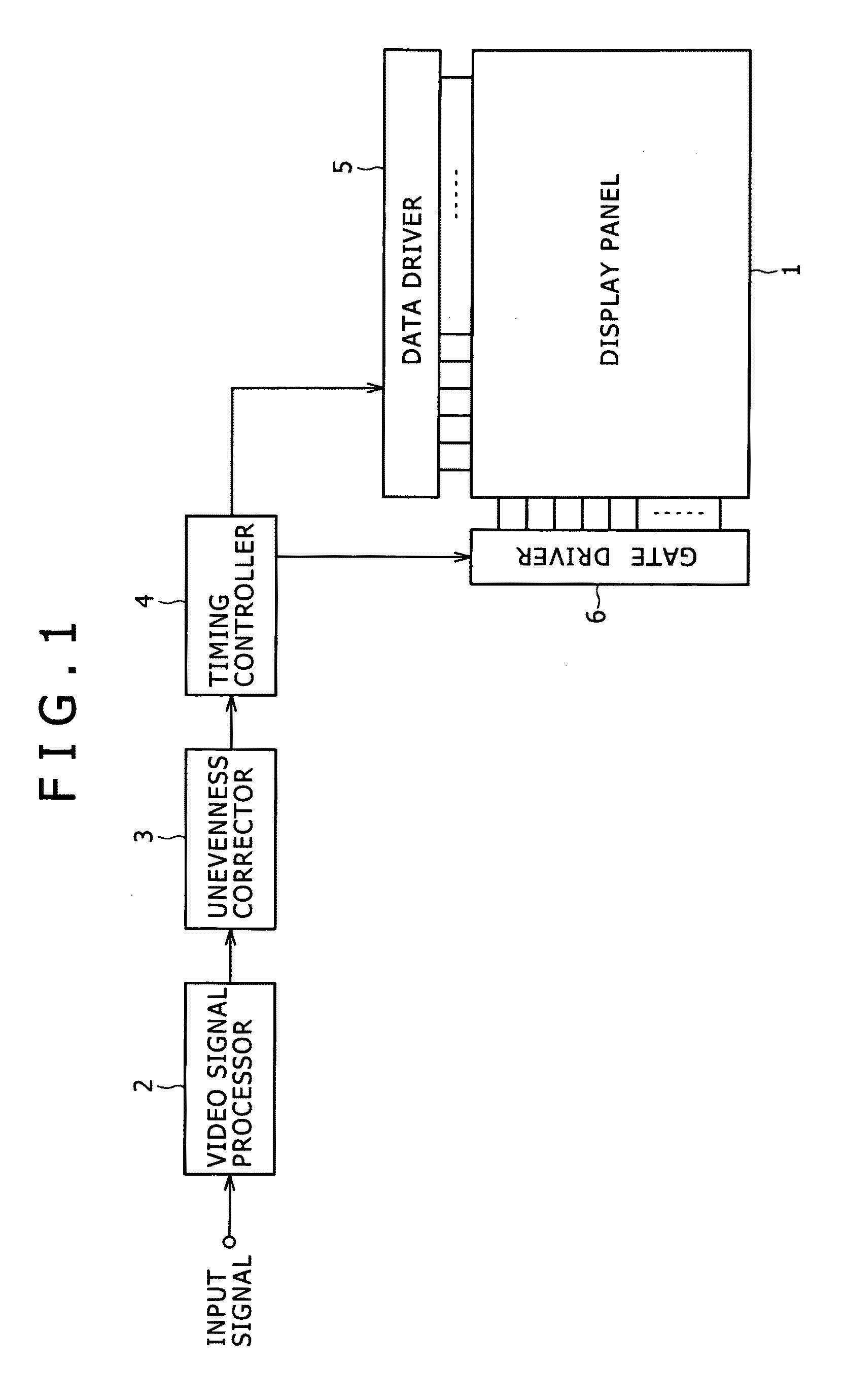
[0066]FIG. 1 is a block diagram of the configuration of major part of a display device according to the embodiment. This display device can be used as a television receiver, a monitor display device, a display device part in various kinds of information apparatus, and so on.

[0067]A video signal processor 2 executes video signal processing in response to an input signal. If the display device is a television receiver for example, the input signal is a received broadcasting signal, and the video signal processor 2 executes processing of extracting a video signal from the received signal. If the display device is video reproduction apparatus, the input signal is a signal read out from a recording medium, and the video signal processor 2 executes video signal reproduction processing. If the display device is network apparatus, the video signal processor 2 executes processing of decoding communication data and so on for...


PUM


Abstract

Disclosed herein is a display device including: a display unit configured to carry out video displaying on a display panel based on a supplied video signal; and a video signal correcting unit configured to output a corrected video signal value obtained through arithmetic operation including division operation in response to an input video signal value, as correction processing suited to a characteristic of the display panel for a video signal to be supplied to the display unit, wherein the video signal correcting unit includes a memory table block having a plurality of reference tables, and a correction operation block that calculates a corrected video signal value through arithmetic operation including all or a part of addition, subtraction, and multiplication by using an input video signal value and the operation result values read out from reference tables dependent upon the input video signal value in the memory table block.

Description

CROSS REFERENCES TO RELATED APPLICATIONS[0001]The present invention contains subject matter related to Japanese Patent Application JP 2007-328181 filed in the Japan Patent Office on Dec. 20, 2007, the entire contents of which being incorporated herein by reference.BACKGROUND OF THE INVENTION[0002]1. Field of the Invention[0003]The present invention relates to a display device, a video signal correction device, and a video signal correction method, and relates to a technique for enhancing the uniformity of displaying by correcting unevenness of the luminance and the chromaticity as characteristics of a display panel.[0004]2. Description of the Related Art[0005]As disclosed in e.g. Japanese Patent Laid-Open No. 2005-195832, an unevenness correction device called a 3D-γ system is put into practical use in order to correct luminance unevenness and chromaticity unevenness of a display device (or display panel, simply) to thereby improve the uniformity thereof. In the 3D-γ system, the cor...

Claims


Application Information

Patent Timeline
Patent Type & Authority Applications(United States)
IPC IPC(8): H04N5/14H04N5/66
CPCG09G3/2092G09G2320/0242H04N21/4318H04N5/57H04N9/68H04N5/20G09G5/10G09G3/34
Inventor KATO, YASUNOBU
Owner SONY CORP
Learn More