Steam valve assembly and steam turbine plant
a technology of steam valves and steam turbines, which is applied in the direction of fluid pressure control, instruments, process and machine control, etc., can solve the problems of high labor intensity, inability to determine the center gravity of the valve body and the valve stem, and the body at the distal end of the valve stem cannot fully contact the valve seat, etc., to achieve the effect of reducing pressure loss, high efficiency and reducing the pressure loss when the valve is in an open position
- Summary
- Abstract
- Description
- Claims
- Application Information
AI Technical Summary
Benefits of technology
Problems solved by technology
Method used
Image
Examples
first embodiment
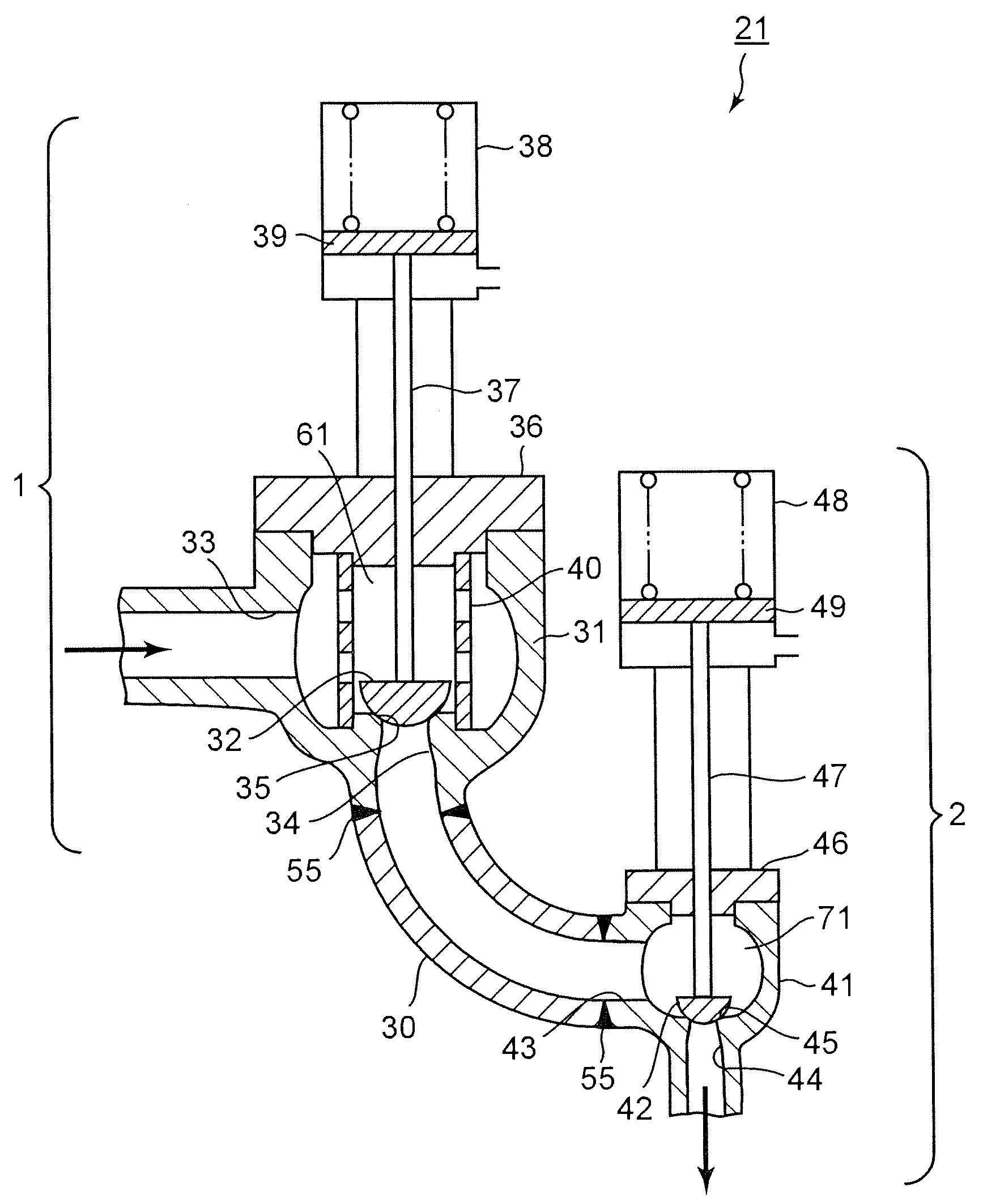
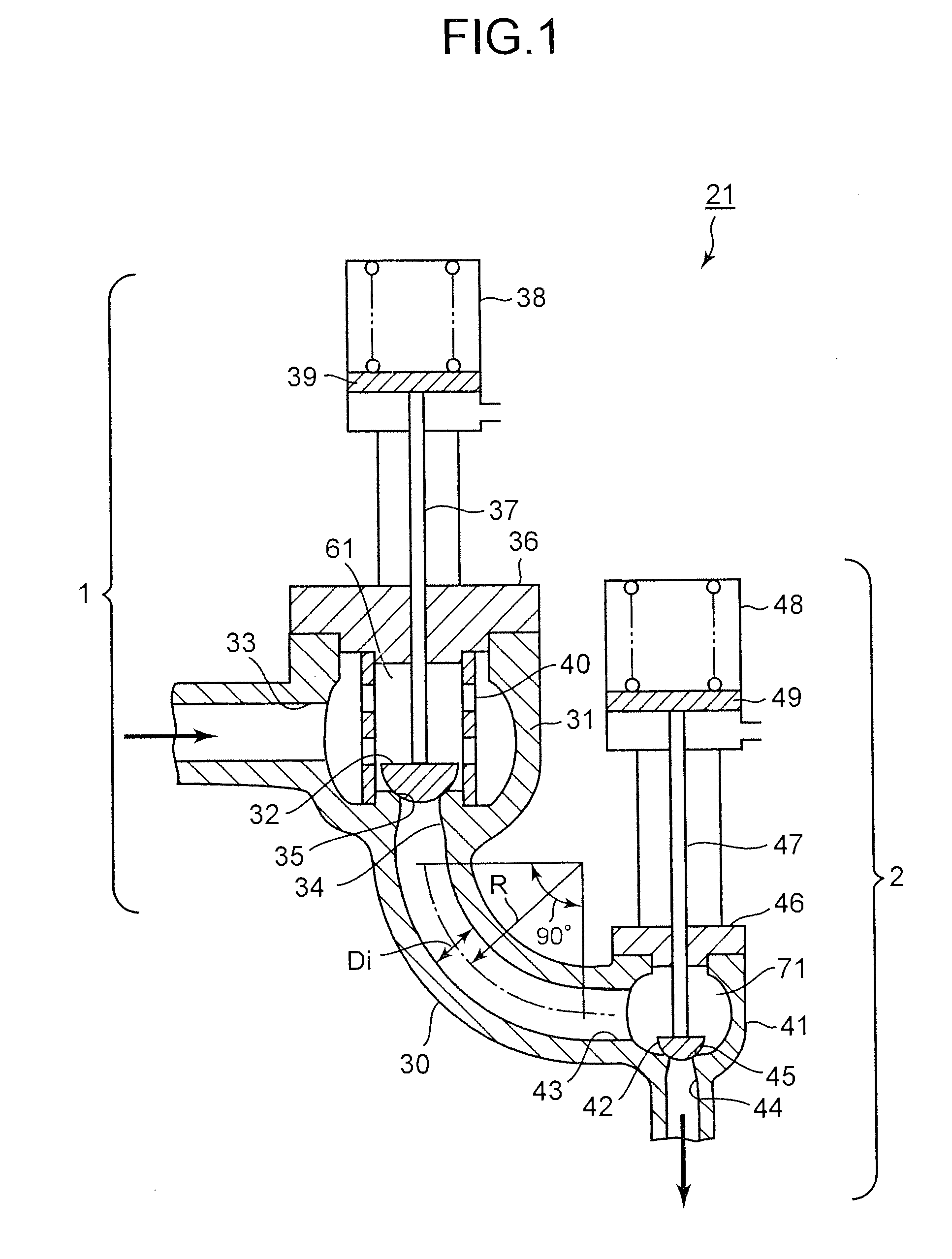
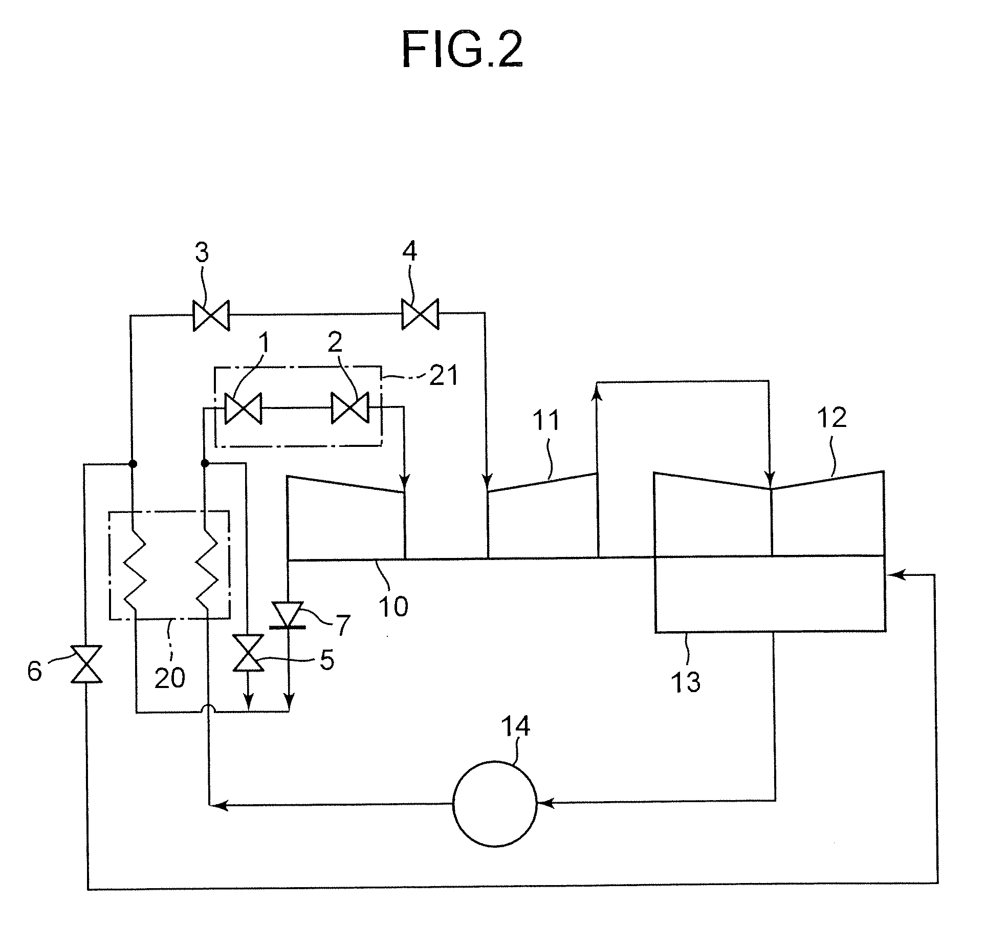
[0020]FIG. 1 is a vertical sectional view showing a first embodiment of a steam valve assembly according to the present invention. FIG. 2 is a system diagram showing a steam turbine plant that has the steam valve assembly according to the present invention.
[0021]The steam turbine plant is so designed that, as shown in FIG. 2, the steam flowing from a boiler 20 is supplied to a high-pressure steam turbine 10 via the steam valve assembly 21. The steam valve assembly 21 has a main-steam stop valve 1 and a steam control valve 2 arranged downstream of the main-steam stop valve 1. The steam that has done work in a high-pressure steam turbine 10 flows through a check valve 7 back into the boiler 20. In the boiler 20, the steam is heated again by a re-heater. The re-heated steam flows through a re-heated steam stop valve 3 and an intercept valve 4 into an intermediate-pressure steam turbine 11, and then to a low-pressure steam turbine 12. Thus, the steam performs work in both the intermedia...
second embodiment
[0038]FIG. 3 is a vertical sectional view showing a second embodiment of the steam valve assembly according to the present invention. The steam valve assembly 21 according to the second embodiment is almost identical in structure to the steam valve assembly according to the first embodiment. During the manufacture of the second embodiment, however, the main-steam stop valve 1, the steam control valve 2, and the intermediate flow path 30 are formed as separate units, each by means of forging or casting. Thereafter, the first casing 31 of the main-steam stop valve 1, the intermediate flow path 30, and the second casing 41 of the steam control valve 2 are connected by, for example, welding, at the junctions 55.
[0039]Fluid is known to flow in such a complex manner as explained in conjunction with the first embodiment. Centrifugal force is applied on that part of fluid, which flows along the center part of the intermediate flow path 30. This part of the fluid is pushed outward to the out...
third embodiment
[0045]FIG. 4 is a vertical sectional view showing a third embodiment of the steam valve assembly according to the present invention. This embodiment is a modification of the first embodiment. In the first embodiment, the intermediate flow path has one arcuate elbow having a bending angle of 90°. In the third embodiment, the intermediate flow path 30 is a combination of an arcuate elbow 50 and a straight flow-path part 51. The elbow 50 is connected to the outlet port (first outlet port) 34 of the main-steam stop valve 1 and has a bending angle of 45°. The straight flow-path part 51 is connected to the lower end of the elbow 50 and obliquely extends downward.
[0046]In this embodiment, the flow separation of the steam flowing in the elbow can be more suppressed, and the pressure loss can be further reduced. The ratio (R / Di) of the radius R of curvature of the elbow 50 to the inner diameter Di of the elbow 50 should preferably be 2 or more as in the first embodiment. Further, in this emb...
PUM
 Abstract
Description
Claims
Application Information
 - R&D
- Intellectual Property
- Life Sciences
- Materials
- Tech Scout
- Unparalleled Data Quality
- Higher Quality Content
- 60% Fewer Hallucinations
Browse by: Latest US Patents, China's latest patents, Technical Efficacy Thesaurus, Application Domain, Technology Topic, Popular Technical Reports.
© 2025 PatSnap. All rights reserved.Legal|Privacy policy|Modern Slavery Act Transparency Statement|Sitemap|About US| Contact US: help@patsnap.com


