
X-ray generator

Inactive Publication Date: 2009-06-18
AET
View PDF9 Cites 41 Cited by
  • Summary
  • Abstract
  • Description
  • Claims
  • Application Information

AI Technical Summary

Benefits of technology

[0022]The X-ray generator of the present invention, applied to the X-ray therapeutic apparatus, is applied to the X-ray therapeutic apparatus being able to vary a relative position of the lesion portion of a patient fixed on a treatment couch and the X-ray generator installed in the X-ray head, irradiating X-rays to the lesion portion of the patient.
[0023]According to the X-ray generator of the present invention, it can provide immediately desired two-dimensional dose distribution by subdividing the radiation dose to need for each part of the lesion portion without using multi-leaf collimator. Even more particularly, the present invention can provide the X-ray therapeutic apparatus which is able to treat effectively a lesion portion with easing burdens of a patient by shortening treatment time and with holding down a dosage to normal cell.

Problems solved by technology

Therefore, the accuracy of dose distribution obtained in the three-dimensional space is not sufficient.
However, when an accuracy of the radiation therapy is going to be raised by using the multi-leaf collimator, a radiation number of times will be increased, burdens of the patient increase to need time for a treatment.
Even more particularly, if a treatment time becomes long, there is a limit in the conventional method of improving treatment accuracy by increasing a radiation number of times because it becomes difficult to fix a lesion portion.
However, because the gantry is heavy, the backlashes and arcuations occur easily while the gantry rotates.
As shown in Japanese Unexamined Patent Application Publication No. 2002-153567, when the resolution higher than ⅓ cm is required, the three-dimensional radiation of radioactive rays after a gantry rotational transferred has a problem in respect of accuracy.
Also, because the leaf of the multi-leaf collimator is rectangular, when the treatment domain has unevenness, it is difficult to position the leaf along the bound of the treatment domain.
Even more particularly, there is a problem to injure normal tissues of the bound vicinity because a leaf malfunctions in the location with a rippling dose distribution in the bound part of the radiation domain.

Method used


Image

  • X-ray generator
  • X-ray generator
  • X-ray generator

Examples


Embodiment Construction

Detailed Description of the Preferred Embodiment 1

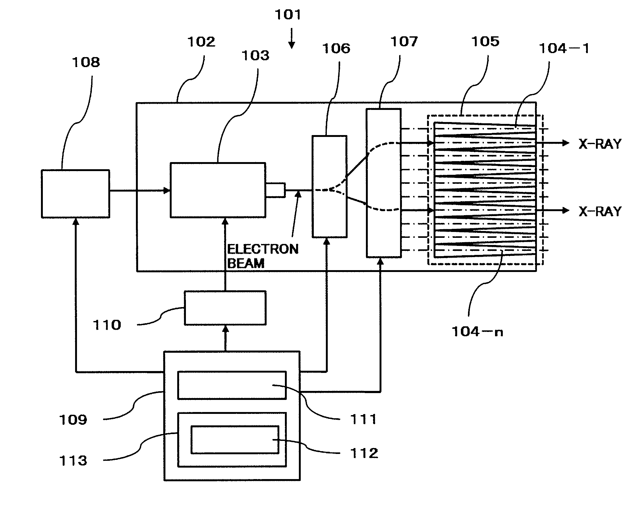
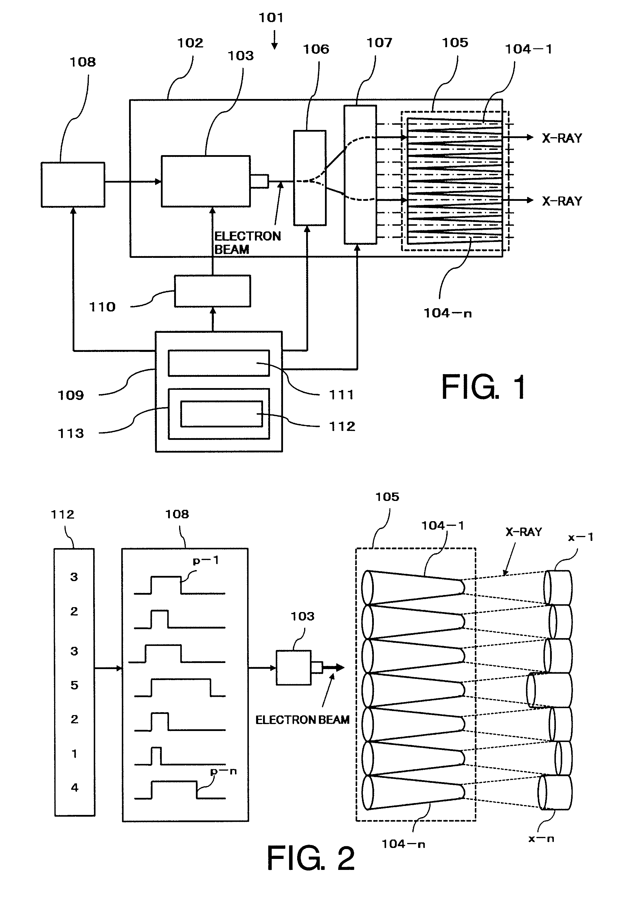
[0040]FIG. 1 shows the schematic representation showing a constitution of the X-ray generator concerning the preferred embodiment 1 of the present invention. In FIG. 1, the X-ray generator 101 comprises an electron source (hereinafter referred to as an electron gun) 103 irradiating high energy electron beams to a vacuum chamber 102, the X-ray target tube array 105 comprises a plurality of X-ray target tubes 104-1 through 104-n arranging in line which irradiates X-ray beams by colliding the high energy electron beams irradiated by the electron gun 103, the first deflection electromagnet 106 and the second deflection electromagnet 107 which deflect the high energy electron beams which are irradiated the electron gun 103. A power source 108 outputting the high energy pulse to the electron gun 103 by a predetermined timing, a microwave source 110 supplying the high voltage microwave to the electron gun 103 and a controller 109 controllin...


PUM


Abstract

The electron beam corresponding to radiation intensity data 112 is output from an electron source 103 by supplying high energy pulse p-1 through p-n corresponding to the radiation intensity data 112 of the radiation field to electron source 103 from power source 108. This electron beam is deflected to be incident in parallel to the medial axis of the X-ray target tube by a deflection means comprising electromagnets, X-ray beam x-1 through x-n which electron beam collides to the inner wall of X-ray target tube 104-1 through 104-n, and have desired intensity is irradiated.

Description

BACKGROUND OF THE INVENTION[0001]1. Field of the Invention[0002]The present invention concerns an X-ray generator irradiating the X-ray beam which the radiation intensity is modulated, in particular, it relates to an X-ray generator can form a new radiation field by bundling up a plurality of X-ray tubes that the radiation field of the X-ray beam is narrow and can set the radiation intensity individually. Even more particularly, the present invention relates to an X-ray generator which is suitable for an X-ray therapeutic apparatus with one or more the X-ray generators.[0003]2. Description of the Related Art[0004]An intensity modulation radiation therapy (it is abbreviated to IMRT as follows.) can reduce a radiation dose to normal tissues around the lesion portion by changing such as a radiation angular degree, a radiation field and a radiation intensity of radioactive rays according to a shape of the lesion portion, so that the radioactive rays concentrate on the lesion portion. Th...

Claims


Application Information

Patent Timeline
IPC IPC(8): H01J35/30
CPCA61N5/1042A61N5/1084H01J2235/086H01J35/14H01J35/08H05G1/52H01J35/112H01J35/153
Inventor TANABE, EIJI
Owner AET
Learn More