
High pressure and high temperature chromatography

a high-temperature, chromatographic technology, applied in the field of chromatography, can solve the problems of slow and inefficient heating and cooling function, unusually harsh ambient conditions in certain environments, such as oil and gas wells, and time-consuming cooling process

Active Publication Date: 2009-06-18
SCHLUMBERGER TECH CORP
View PDF6 Cites 25 Cited by
  • Summary
  • Abstract
  • Description
  • Claims
  • Application Information

AI Technical Summary

Benefits of technology

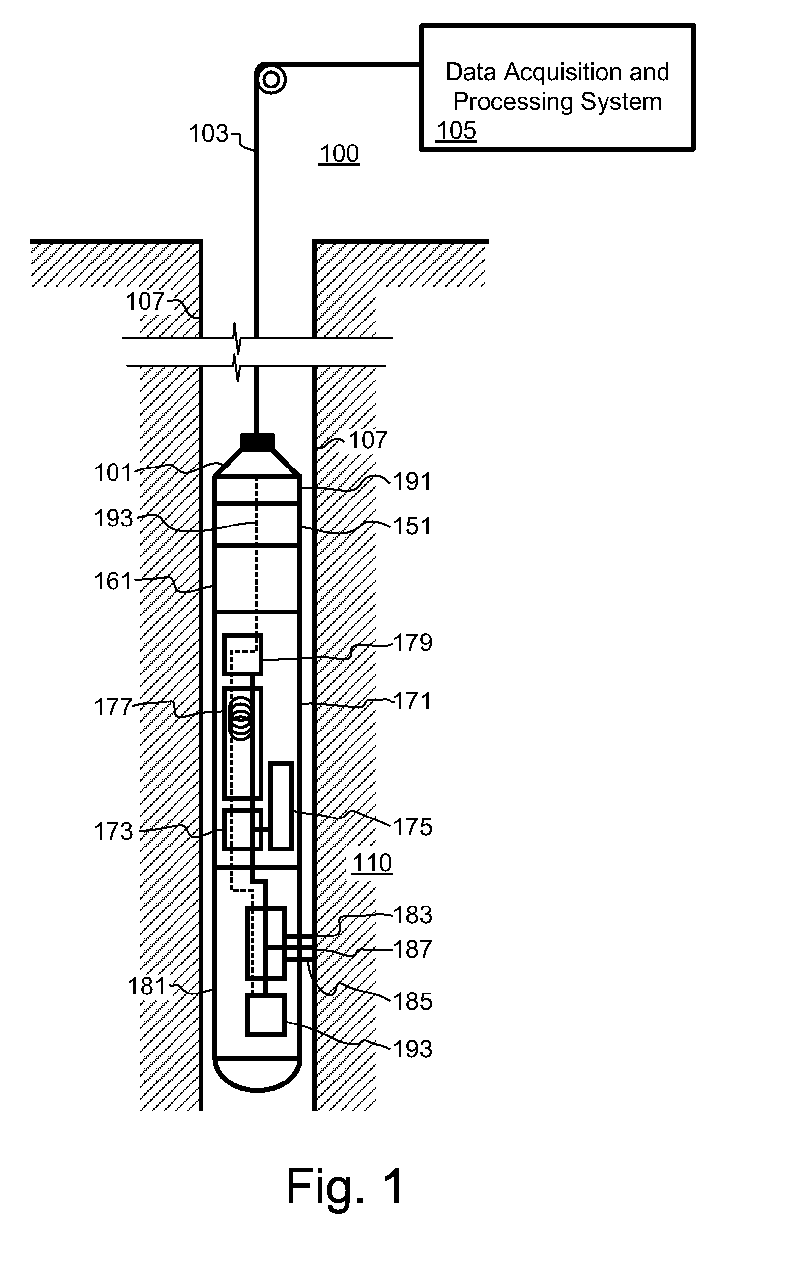
[0009]According to embodiments, a system for chromatographic analysis of a sample containing a plurality of components is provided. The system includes a flowpath adapted to flow a mobile phase and the sample at high pressures; an injector adapted to inject the fluid sample into a flowpath; a separation column adapted to operate at high pressures, forming part of the flowpath downstream of the injector, for separating a plurality of components within the fluid sample; a detector located downstream of the column, thereby generating measurement data representing properties of at least one component of the fluid sample; and a processor adapted calculate from the measurement data a value relating to the amount of at least one component of the fluid sample. According to certain embodiments, the system can operate a pressures above 20 atm or even 100 atm, and temperatures above about 100 degrees Celsius. According to certain embodiments the system also includes a tool housing constructed and adapted to be deployed in a wellbore in a subterranean rock formation; and a fluid collection system for obtaining the fluid sample downhole, wherein the flowpath, injector, column and detector are housed within the tool housing and adapted to operate under downhole conditions. According to other embodiments, the system is in close proximity to a wellhead and includes a tap in fluid communication with a surface flowline carrying produced fluids and the injector.

Problems solved by technology

The cooling process can be particularly time consuming unless means of cooling such as fan, thermal switch, etc. is provided.
However, the heating and cooling apparatus contributes significantly to the total mass, which makes the heating and especially the cooling function slow and inefficient.
Certain environments, such as oil and gas wells, have unusually harsh ambient conditions.
Such methods pose significant challenges for implementing chromatography equipment in downhole environment.
Additionally, for the high temperature downhole environment, it is difficult to reject heat from the column / heater / cooler apparatus.
This transportation process to the laboratory takes a significant amount of time which can be very costly for some applications such as off shore operations.
However, these prior systems and methods were primarily concerned with understanding pressure relationships with retention time and did not attempt to propose any techniques for optimizing resolution at high pressures.

Method used


Image

  • High pressure and high temperature chromatography
  • High pressure and high temperature chromatography
  • High pressure and high temperature chromatography

Examples


Embodiment Construction

[0023]The particulars shown herein are by way of example and for purposes of illustrative discussion of the embodiments of the present invention only and are presented in the cause of providing what is believed to be the most useful and readily understood description of the principles and conceptual aspects of the present invention. In this regard, no attempt is made to show structural details of the present invention in more detail than is necessary for the fundamental understanding of the present invention, the description taken with the drawings making apparent to those skilled in the art how the several forms of the present invention may be embodied in practice. Further, like reference numbers and designations in the various drawings indicated like elements.

[0024]FIG. 1 shows a downhole system for chromatographic analysis of a downhole collected fluid sample, according to embodiments. Wireline logging system 100 has a chromatographic analysis tool 171. In wireline well logging, ...


PUM

PropertyMeasurementUnit
pressuresaaaaaaaaaa
pressuresaaaaaaaaaa
temperaturesaaaaaaaaaa

Abstract

Methods and related systems are described for high pressure chromatographic analysis. The described system includes a flowpath adapted to flow a mobile phase and the sample at high pressures, an injector adapted to inject the fluid sample into a flowpath, a separation column adapted to operate at high pressures for separating various components, a detector and a processor that calculates the amount of at least one component of the fluid sample. The system can operate a pressures above 20 atm or even 100 atm, and temperatures above about 100 degrees Celsius. The system can deployed in a wellbore in a subterranean rock formation, and include fluid collection system for obtaining the fluid sample downhole. The system can also be located close to a wellhead and includes a tap in fluid communication with a surface flowline carrying produced fluids and the injector.

Description

BACKGROUND OF THE INVENTION[0001]1. Field of the Invention[0002]This patent specification relates to chromatography. More particularly, this patent specification relates to systems and methods for chromatography under high-pressure and / or high temperature environments.[0003]2. Background of the Invention[0004]Chromatography is the field of separating chemicals based on differences in properties such as volatility, absorption, adsorption, size, etc. In this field, different rates of migration along a given flow path (gas, liquid, supercritical fluid, etc) result in the spatial separation of chemical analytes. This differential migration is achieved by differing rates of interaction with the separation column or by different values of analyte mobility.[0005]Typical gas chromatography (GC) separation columns are small diameter tubes that can be more than 15 meters long. The column, usually wound in a coil, is housed inside a heated compartment or co-wound with heater wires. The heater ...

Claims


Application Information

Patent Timeline
Patent Type & Authority Applications(United States)
IPC IPC(8): G01N30/02
CPCE21B47/10G01N30/22G01N30/32G01N2030/8854G01N33/2823G01N2030/8809G01N30/88
Inventor SHAH, JAGDISHBOSTROM, NEIL WILLIAMZHDANEEV, OLEGRAGHURAMAN, BHAVANIPASO, KRISTOFER GUNNAR
Owner SCHLUMBERGER TECH CORP
Learn More