External fixation clamp

a clamp and external technology, applied in the field of inserts, can solve the problems of loose connection, inability to find suitable material pairings with which to achieve sufficient fixation, and loss of gripping power of connections that have been tightened

Active Publication Date: 2009-06-11
STRYKER EURO OPERATIONS HLDG LLC
View PDF25 Cites 15 Cited by
  • Summary
  • Abstract
  • Description
  • Claims
  • Application Information

AI Technical Summary

Benefits of technology

[0007]It is an aspect of the present invention to provide an insert for a clamping element that allows insertion of rod-shaped elements from the side, and whereby the clamping element, used double, can be inserted directly as an articulated connection, whereby the aforementioned elements of the clamping element can consist of a non-metallic material, for example plastic, without any impairment of the safety of the resulting articulated connection in an external fixator.
[0008]Furthermore, it is an aspect of the present invention to provide a simple clamping element designed for use of such inserts.
[0010]It is one goal of the invention to offer a suitable system that allows an optimal and, to the greatest extent possible, a direct friction lock between the connecting clamp and the rod-shaped elements, which remains constant. At the same time, the locking does not result in overly great stress on the plastic parts and therefore helps to prevent structural damage. The permanent stability of frame configurations for external fixators, which are predominantly made of plastic, is guaranteed, in other words the reliability known from previous metal designs is assured. Furthermore, this design should be a design that can be easily produced and advantageously assembled, in order to obtain a relatively inexpensive product.
[0012]The insert may be either angled or L-shaped. The first part of the L-shaped including a bore for receiving the locking shaft with the second L-shaped portion extending through a passageway in at least one of the jaw members and into engagement with the cavity housing the rod. The tapered edge of the insert may be in the form of a plurality of points or may have a roughened surface for better biting into and engaging the rod and preventing its motion. The tapered engagement edge can extend both axially along the rod and perpendicular thereto to better prevent axial motion of the rod within the cavity. The insert may include an anti-rotation feature to prevent the insert from rotating out of alignment with the axis of the cavity. This can be accomplished by having a portion of the insert in the region of the bore engaging the locking shaft or a portion of the insert engaging a recess in the jaw member. Preferably, the passageway runs from the outside of the jaw member through the jaw member in a direction that is perpendicular to the axis of the cavity and through a surface that delimits the cavity so that the first part of the insert clamp can lie against the clamp outer surface with the second part extending generally at 90° thereto extending into the cavity which receives the rod. In a preferred embodiment of the outer side of the jaw with the insert has a recess extending along the face of the jaw member and recessed in the direction of the passageway to receive the first part of the jaw. The recess is sized to receive the first part of the insert as a press-fit so that the insert is retained on the outer side of the jaw member and is prevented from rotation with respect thereto. Also in the preferred embodiment the bore in the first part for receiving the locking shaft may be oblong so that the jaw member with the insert press-fit therein can be moved apart when a rod-shaped element is inserted in a direction perpendicular to the axis of the cavity. In a second embodiment the jaw member may have a beveled surface for engaging a beveled surface on the insert to provide support for the insert when engaging the rod.
[0013]In particular, an insert according to the invention allows a direct transfer of force from the screw or another locking element to the rod, in order to relieve stress on the plastic component.

Problems solved by technology

If the modules or parts of such a clamp are made of plastic injection-molded materials, there may be the difficulty in finding suitable material pairings with which sufficient fixation can be achieved.
This is a problem particularly because many plastics are characterized by negative creep behavior, which causes connections that have been tightened to gradually come loose, i.e. to lose their gripping power.
Another problem that arises with such configurations is the high pressure stress on the plastic parts when the screw connection has been tightened, and this stress can result in stress cracks due to irregular stress on the plastic structure.
This is particularly dangerous because such defects only occur after a certain period of time, and are not clearly evident optically.

Method used


Image

  • External fixation clamp
  • External fixation clamp
  • External fixation clamp

Examples


first embodiment

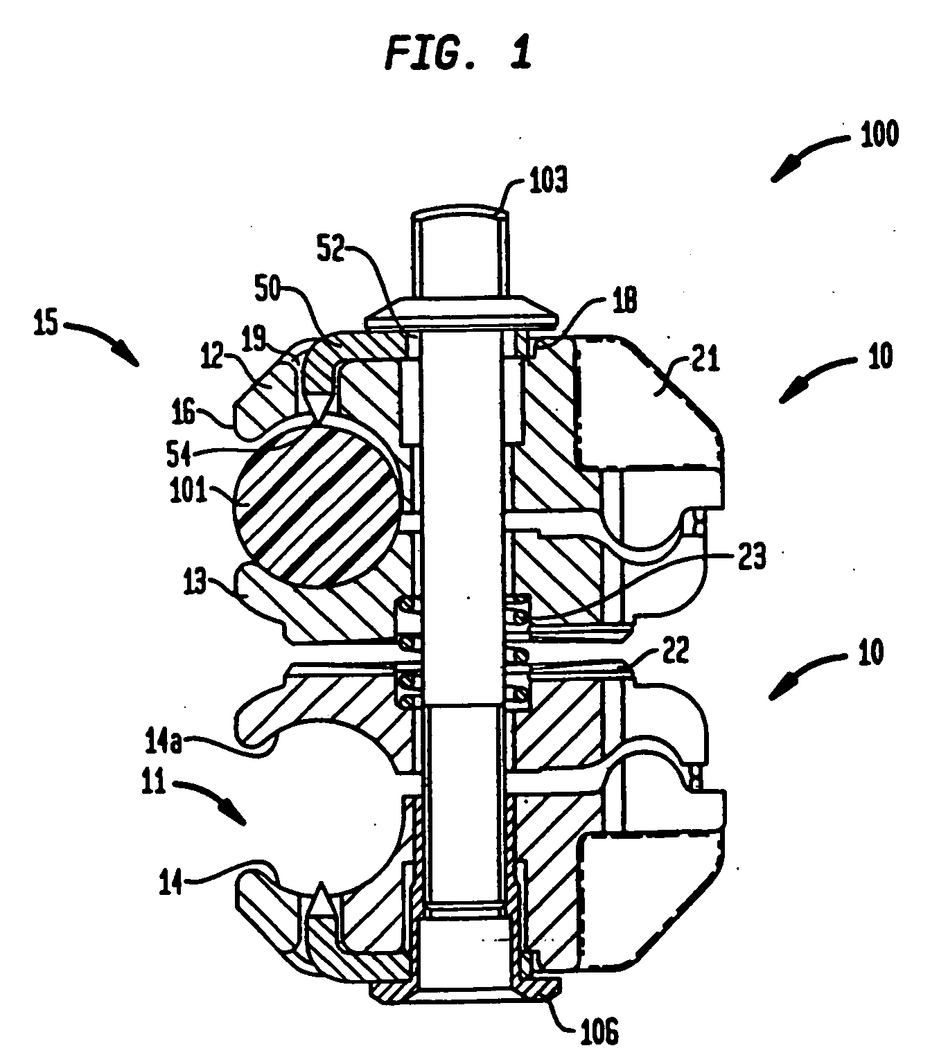
[0047]FIG. 2 shows a perspective view of the first embodiment according to the invention, with an inserted rod 101. The same characteristics in the drawings are shown with the same reference symbols, in each instance. In lower clamping element 10, the break-through of slit bore 19 and two teeth of lower insert 50, which is held by the nut 106, can be seen. Here, the connection between clamping elements 10 is pressed apart by way of a pressure spring 23 that has been inserted between them.

[0048]FIG. 3 shows a perspective view of insert 50 according to the first embodiment, FIG. 4 shows a bottom view of this insert 50, and FIG. 5 shows a side view of the insert 50. In the top view, the insert 50 is essentially a rectangular plate having an oblong bore 52. In cross-section, the insert 50 looks like an L-shaped small plate having a long side 51 and a shorter engagement side 53. Here, the free end of the shorter engagement side 53 ends in two teeth 54, which have a prism shape in cross-s...

second embodiment

[0049]FIG. 6 shows a perspective view of an insert 60 according to a FIG. 7 shows a bottom view of the insert 60 according to FIG. 6, and FIG. 8 shows a side view of the insert 60 according to FIG. 6. The insert 60 is essentially very similar to insert 50, with the difference that here, four teeth 64 are provided, and that the engagement edge 65 of the teeth 64, in each instance, stands crosswise to the longitudinal direction of rod 101, into which it can engage. Therefore the engagement edge 65 of the teeth 64 stands essentially crosswise to the direction of rod 101 and prevents axial displacement of the clamping element 10 on rod 101, in particularly excellent manner.

[0050]FIG. 9 shows a perspective view of on insert 70 according to a third exemplary embodiment, FIG. 10 shows a bottom view of the insert according to FIG. 9, and FIG. 11 shows a side view of the insert according to FIG. 9. In this embodiment variant, the first and second exemplary embodiments are combined, in princ...

sixth embodiment

[0060]FIG. 20 shows a perspective view of an insert 190 according to a FIG. 21 shows a side view of the insert 190 according to FIG. 20, and FIG. 22 shows a bottom view.

[0061]Insert 190 is configured to be rectangular with rounded corners, and, similar to insert 50, has a plate surface 51 that makes a transition into the engagement side 93 on one side, at a slant. This can be achieved by means of punching, for example. The angle between the surface 51 and the engagement side 93 can be 45 degrees, for example, but other values, advantageously between 30 and 60 degrees, are also possible. An oblong hole 92 is disposed in the surface 51; its longitudinal direction is oriented perpendicular to the punch line of the engagement side 93. The smaller diameter of the oblong hole 92 essentially corresponds to the diameter of the screw 103 provided for the clamping element 30 according to FIG. 23. Oblong hole 92 has a region that extends into the slant of the engagement side 93. This is advan...


PUM


Abstract

An insert for an external fixation has two jaws for clamping a rod-shaped element. The insert includes a locking element and is an angled piece having two free ends, with at least one engagement edge for engagement into the rod-shaped element being provided at its one free end. The insert has a recess or bore for engagement with a locking shaft of the clamp provided at the free end thereof that lies opposite to the free end having the rod engagement edge. The insert is angled so that it may extend through a passageway in one of the jaws and into a cavity formed in the jaw for receiving the rod. The insert rod engaging edges are tapered to bite into the rod to prevent its movement.

Description

CROSS-REFERENCE TO RELATED APPLICATION[0001]This application is a divisional of U.S. application Ser. No. 11 / 120,775, filed on May 3, 2005, the disclosure of which is incorporated herein by reference.BACKGROUND OF THE INVENTION[0002]The invention relates to an insert for a clamping element for clamping a rod-shaped element of an articulated connection, particularly for a clamping element of an articulated connection for stabilizing bone fractures. Furthermore, the invention relates to an articulated connection having two clamping elements and having a locking element. In particular, the invention relates to an insert for optimizing the fixation of round rods in an external fixation system.[0003]An articulated connection is known from U.S. Pat. Nos. 5,741,252, 5,752,954, 6,080,153, 6,342,054, 6,616,664, and 6,702,814, respectively, which consists of two or four individual clamping jaw elements and a central shaft or screw. In the case of this articulated connection, it is possible to...

Claims


Application Information

Patent Timeline
Patent Type & Authority Applications(United States)
IPC IPC(8): A61B17/70
CPCA61B17/645A61B17/6466F16B7/0433Y10T403/69Y10T403/7141Y10T403/7062Y10T403/595Y10T403/581Y10T403/7105F16B2200/69
Inventor THOMKE, ROLANDBURGHERR, VINZENZFANKHAUSER, DAMIAN
Owner STRYKER EURO OPERATIONS HLDG LLC
Why Eureka
Try Eureka