
RFID tag and method and device for the production thereof

a technology of rfid tags and tags, which is applied in the field of rfid tags, can solve the problems of affecting the wearing comfort, difficult production of multi-layer rfid tags, and inflexibility of rfid tags, so as to improve the flexibility of rfid tags and therefore their handling and wearing comfor

Inactive Publication Date: 2009-06-11
TEXTILMA AG
View PDF3 Cites 12 Cited by
  • Summary
  • Abstract
  • Description
  • Claims
  • Application Information

AI Technical Summary

Benefits of technology

[0008]The fact that the antenna is incorporated into or applied to the carrier layer means that the chip is also arranged directly on the carrier layer and connected to the antenna and thus forms a transponder tag which is connected directly to the design tag. There is thus an RFID tag that has only two layers, which is much thinner and shows much less than the known three-layer RFID tags. This improves the flexibility of the RFID tag and therefore its handling and wearing comfort.
[0009]It is particularly advantageous if the antenna is arranged in the form of a meander or zigzag, which means in particular that knitting or weaving the antenna into a knitted or woven carrier layer is possible. If appropriate, such an antenna can however also be printed or vapor-deposited onto a carrier layer. The antenna can be arranged in the manner of a coil. Preference is given to the formation of the transponder with an RFID chip. If appropriate, the RFID tag can also contain a transponder which has an HF or UHF chip. The configuration of an RFID tag is particularly advantageous, the carrier layer being knitted or woven, so that the antenna can be knitted in or woven in.
[0012]A particularly simple method results if the transponder tag strip or the transponder tag is fed to the connecting station at an angle α with respect to the design tag strip and is connected to the design tag strip in the region of the leading edge of the transponder tag.

Problems solved by technology

Such RFID tags are relatively complicated and not very flexible and, when used in items of clothing, form undesired discontinuities, which impair the wearing comfort.
This multi-layer RFID tag is not only difficult to produce but also relatively thick and rigid and thus exhibits the same undesired properties as the RFID tag described above.

Method used


Image

  • RFID tag and method and device for the production thereof
  • RFID tag and method and device for the production thereof
  • RFID tag and method and device for the production thereof

Examples


Embodiment Construction

[0030]FIGS. 1 and 2 show an RFID tag 2 which has a design tag 4, on the rear side 6 of which there is arranged a transponder tag 8. This transponder tag 8 has a carrier layer 10, in which an antenna 12 is arranged in the form of a meander. A chip 14 has lugs 16, by means of which the chip is connected to antenna sections 18, 20. The antenna sections 18, 20 are provided on a short-circuit bridge 22 having an interruption 24. The transponder tag 8 is somewhat shorter than the design tag 4 and, for example, is adhesively bonded or welded to the design tag at a connecting point 26 in the region of the leading edge of the transponder tag.

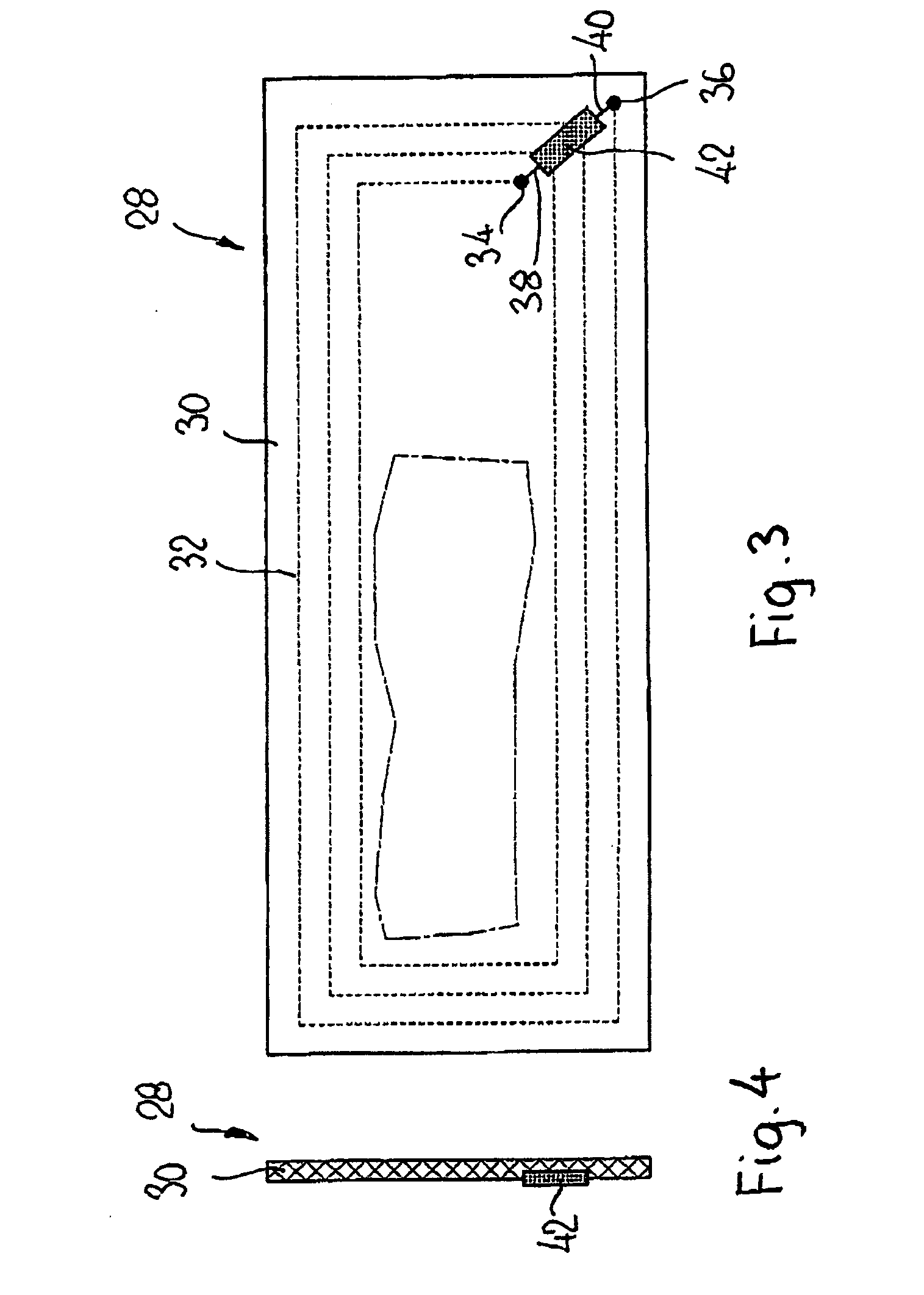
[0031]FIGS. 3 and 4 show a further transponder tag 28, which has a carrier layer 30 on which an antenna 32 is arranged in the manner of a coil, the ends 34, 36 of which are connected to terminals 38, 40 of a chip 42. Such a transponder tag 28 can also be connected to a design tag of the type described in FIGS. 1 and 2.

[0032]The transponder tags shown in ...


PUM

PropertyMeasurementUnit
Angleaaaaaaaaaa
Lengthaaaaaaaaaa

Abstract

Disclosed is an RFID tag comprising a textile design tag (4), on the rear face (6) of which a transponder is arranged that is provided with a chip (14) comprising an antenna (12). In order to create a simplified and thinner RFID tag, the antenna (12) is incorporated into or is applied to a support layer (10) and is connected to the chip (14) in the form of a transponder tag (8) which is connected directly to the design tag (4).

Description

[0001]This application is a continuation-in-part of PCT / CH2007 / 00025 1 filed on May 16, 2007 designating the U.S. and claiming priority from CH 1194 / 06 filed on Jul. 24, 2006, the disclosures of which are incorporated herein by reference.TECHNICAL FIELD[0002]The invention relates to an RFID tag and a method and a corresponding device for the production of the RFID tag.BACKGROUND OF THE INVENTION[0003]WO02093524 A has disclosed an RFID tag in which a complete transponder comprising an antenna arranged on a carrier and having a connected chip is first transferred to a carrier layer, which is then connected to a design tag, the latter reaching over the carrier layer in the manner of a hem. Since the transponder is present as a unit, it forms its own layer and thus leads to a three-layer and therefore relatively thick and rigid RFID tag. Such RFID tags are relatively complicated and not very flexible and, when used in items of clothing, form undesired discontinuities, which impair the w...

Claims


Application Information

Patent Timeline
IPC IPC(8): H04Q5/22
CPCB65H35/04G06K19/07783B65H39/16B65H2301/4382B65H2701/1244B65H2701/192B65H2701/1942D06H1/04G06K19/027G06K19/0723G06K19/07718G06K19/07749G06K19/07758G06K19/07779B65H37/04B31D1/02G06K19/077G08B13/24
Inventor SPEICH, FRANCISCO
Owner TEXTILMA AG
Learn More