Eureka AIR delivers breakthrough ideas for toughest innovation challenges, trusted by R&D personnel around the world.

Wireless and wired control mechanism for an aerial lift or crane

a control mechanism and wired technology, applied in the direction of load-engaging elements, lifting devices, transportation and packaging, etc., can solve the problems of radio signal interference and limit the ability to control the crane or lift function

Inactive Publication Date: 2009-06-11
BOND ANTHONY E
View PDF7 Cites 29 Cited by
  • Summary
  • Abstract
  • Description
  • Claims
  • Application Information

AI Technical Summary

Benefits of technology

"The patent describes an aerial lift or crane that has a control mechanism mounted on a vehicle. This control mechanism includes a radio receiver and a control box that can be hard wired or wireless connected to the vehicle. The operator can control various functions of the boom and other components of the crane from the work platform or from the ground using the wireless connection. The control box can be easily moved within the work platform or removed from it for more flexibility. The wireless control mechanism allows the operator to have more freedom of movement and control the functions of the boom or crane. Additionally, the wireless control mechanism does not drain the battery during periods of boom or crane operation."

Problems solved by technology

Radio signals are transmitted from the operator on the work platform to the control means located on the vehicle and function generally satisfactorily, but, in some cases, the radio signals suffer from interference.
Typically, the connector or tether is 20 to 30 feet long and thereby limits the ability to control the crane or lift functions due to the length of the connector or tether at ground level.

Method used


Image

  • Wireless and wired control mechanism for an aerial lift or crane
  • Wireless and wired control mechanism for an aerial lift or crane
  • Wireless and wired control mechanism for an aerial lift or crane

Examples


Embodiment Construction

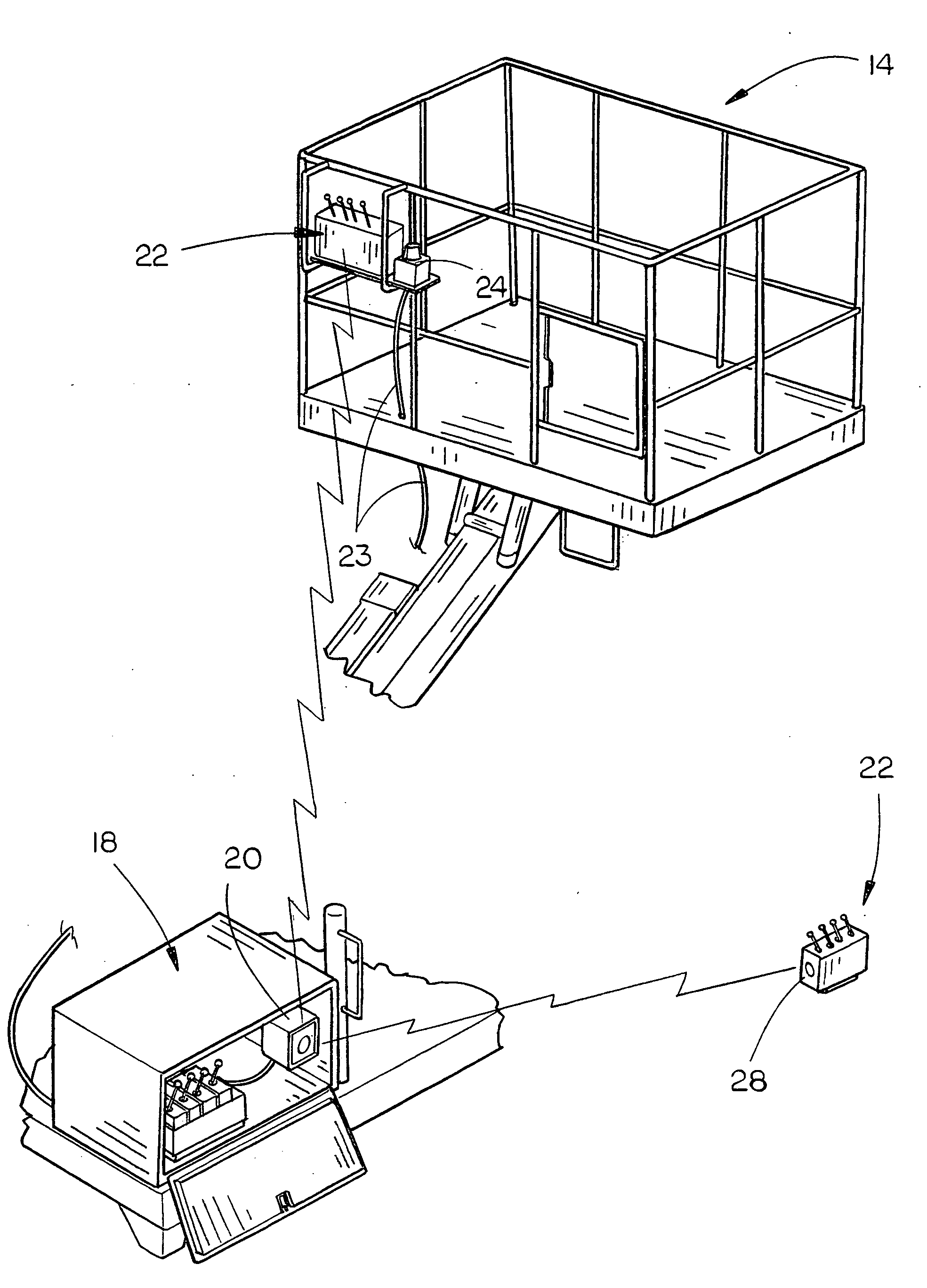
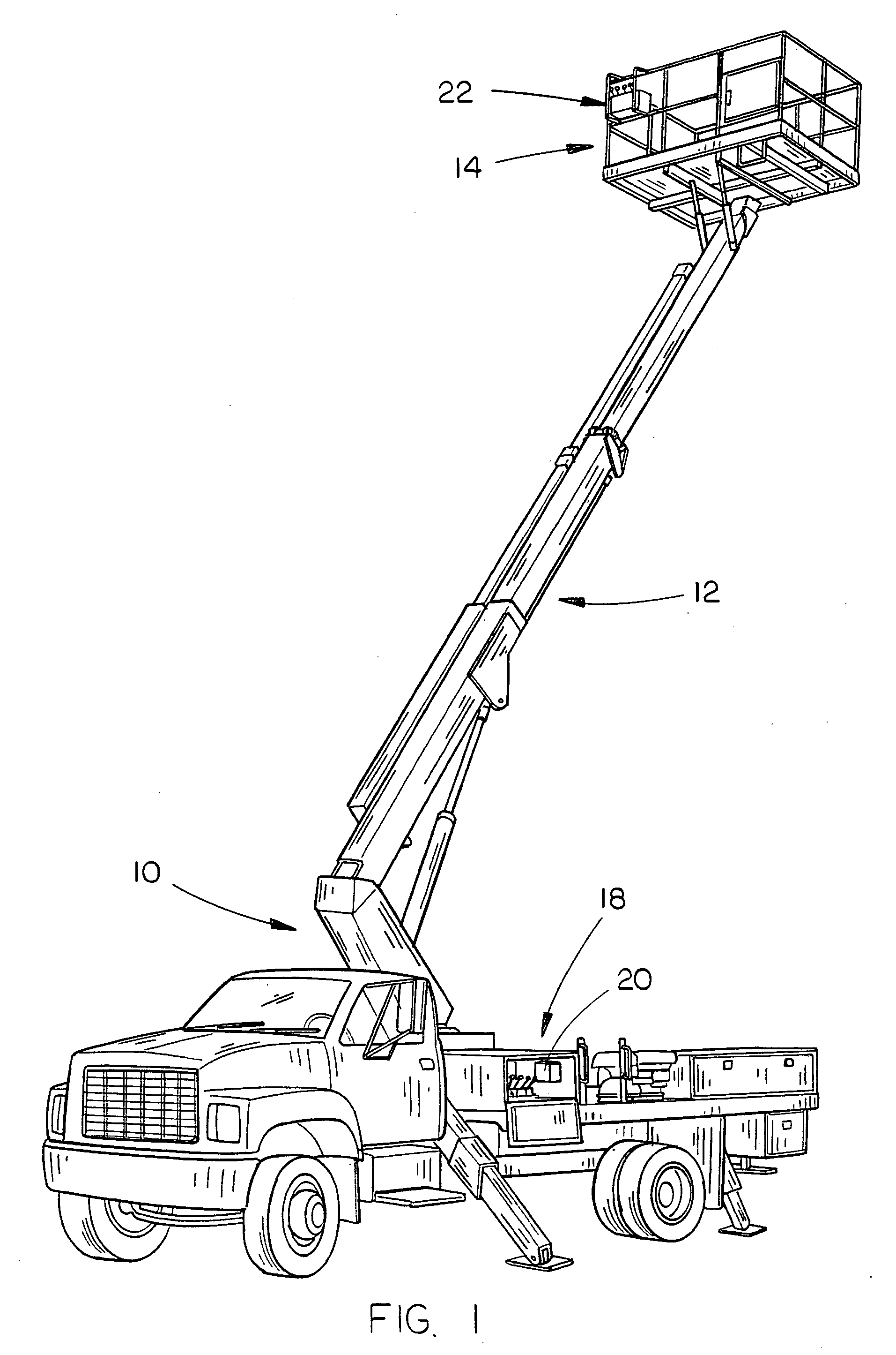
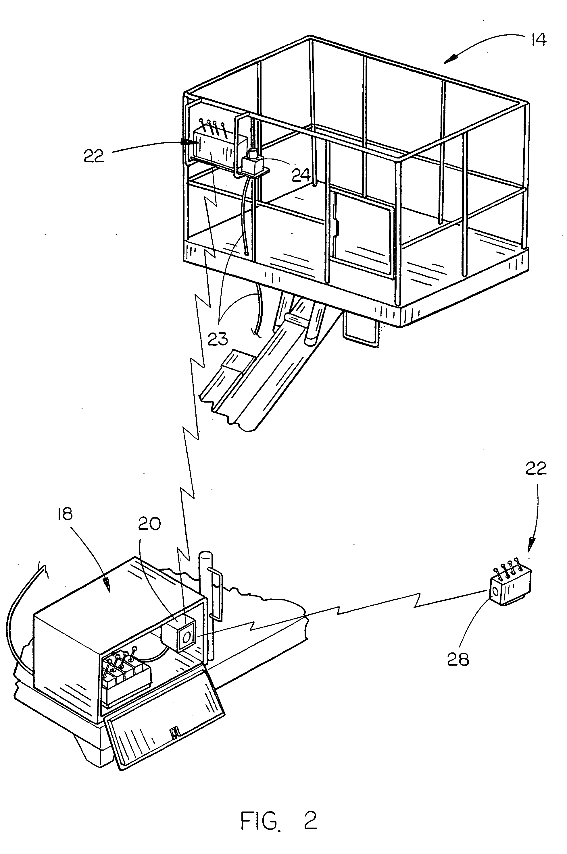
[0014]The numeral 10 refers generally to a truck-mounted aerial lift including a telescoping boom 12 having a work platform 14 mounted on the outer end of the boom 12 which may or may not be removable therefrom. In many cases, the outer end of the telescoping boom 12 will have a pulley or sheave over which a lifting or hoisting cable may be extended so that the aerial lift may function as a crane. The aerial lift 10 includes a control means 18 which is normally located behind the cab of the aerial lift or at one side of the aerial lift. The control means 18 includes a radio receiver 20 which normally interprets the transmitter frequencies, and delivers voltage output to a hydraulic valve after the hydraulic valve receives the voltage output from the receiver 20, then an appropriate boom function will occur.

[0015]A control box 22 is selectively removably mounted to one side of the work platform 14 and includes the normal levers, joysticks, etc. The control box 22 is hard wired to the...


PUM


Abstract

A wireless and wired control mechanism is provided for an aerial lift or crane wherein a control box is located within the work platform of the aerial lift. The control box is hard wired to a radio receiver in the control mechanism of the aerial lift or crane. The control box is also wireless connected to the control mechanism which permits a radio transmitter in the control box to transmit signals to the control mechanism when the hard wired connection between the control box and the control mechanism is disconnected. The control box is conveniently movable within the work platform and may be completely removed therefrom so that an operator may control the functions of the aerial lift or crane from the ground by way of the wireless connection.

Description

CROSS-REFERENCE TO RELATED APPLICATION[0001]This application claims the benefit of U.S. Provisional Application Ser. No. 60 / 898,954 entitled “WIRELESS AND WIRED CONTROL MECHANISM FOR AN AERIAL LIFT OR CRANE” filed Feb. 1, 2007, the disclosure of which is hereby incorporated herein by reference.BACKGROUND OF THE INVENTION[0002]1. Field of the Invention[0003]This invention relates to a wireless and a hard wired control mechanism for an aerial lift or crane and more particularly to a control box which is located on the aerial work platform mounted on the outer end of the telescoping boom of the aerial lift or crane with the control box being hard wired to the control means for the aerial lift or crane and having wireless connection to the control means by means of a wireless transmitter / receiver connection.[0004]2. Description of the Related Art[0005]Aerial lifts typically comprise a telescoping boom mounted on a vehicle such as a truck or the like with a work platform being mounted on...

Claims


Application Information

Patent Timeline
Patent Type & Authority Applications(United States)
IPC IPC(8): B66C13/44
CPCB66F11/046B66C13/44
Inventor BOND, ANTHONY E.
Owner BOND ANTHONY E
Why Eureka
Eureka Blog
Learn More