
Charging system of electric powered vehicle

Inactive Publication Date: 2009-06-04
TOYOTA JIDOSHA KK
View PDF2 Cites 87 Cited by
  • Summary
  • Abstract
  • Description
  • Claims
  • Application Information

AI Technical Summary

Benefits of technology

[0013]According to the above-described charging system of the electric powered vehicle, by receiving the advertising information selected based on at least one of the charged vehicle information stored inside the relevant electric powered vehicle and the facility information of the relevant charging facility at the time of external charge, at least part of the charging power fee can be caused to be borne by the advertising provider. As a result, by giving an economic merit to the user of the electric powered vehicle, incentive for external charge can be enhanced. Also, the advertising provider side, based on the charged vehicle information and / or the facility information, can appropriately select the electric powered vehicle that can be expected in advertising effect and send the advertising information, which makes the acquisition of the advertising provider easy. Furthermore, the motivation for the installation of the charging facility can be given because business by advertising income is also enabled, and contribution to popularization and expansion of the electric powered vehicle by well-developed infrastructure can also be expected.
[0016]The above-described configuration allows the advertising information to be reproduced efficiently and in an aspect that will increase an adverting effect, in conjunction with the navigation system.
[0020]Accordingly, a main advantage of this invention lies in that the charging system of the electric powered vehicle that can give incentive for external charge to the user of the electric powered vehicle can be established.

Problems solved by technology

In this respect, in the configuration of Patent Document 1, a merit of the external charge is only to obtain the information of a product or service suitable for the vehicle and the user, so that there is a concern that an appealing effect is insufficient for the expanded use of the external charge.

Method used


Image

  • Charging system of electric powered vehicle
  • Charging system of electric powered vehicle
  • Charging system of electric powered vehicle

Examples


Embodiment Construction

[0030]Hereinafter, referring to the drawings, an embodiment of the present invention is described in detail. Hereinafter, the same or equivalent parts in the drawings are given the same reference numerals and signs, and in principle, description thereof is not repeated.

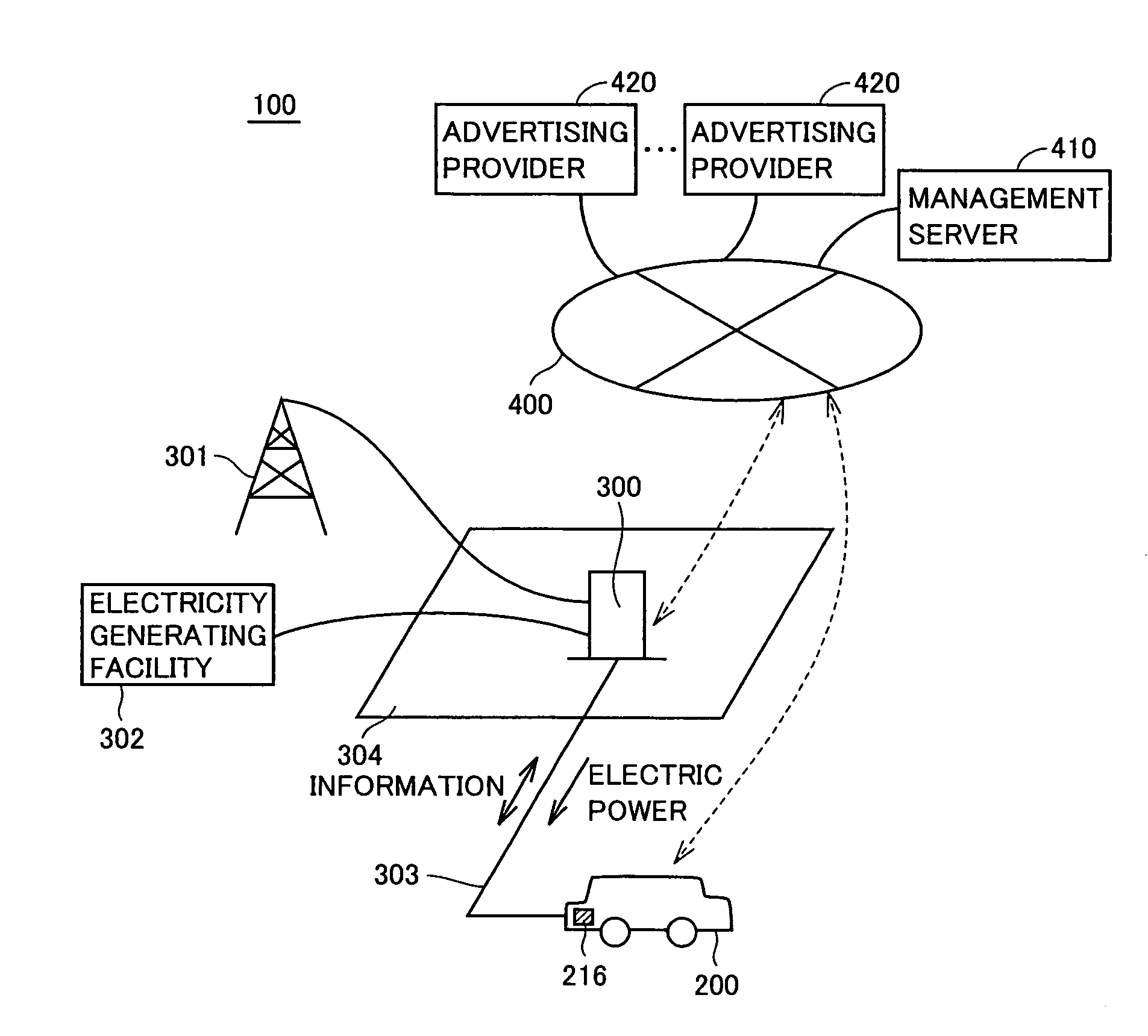
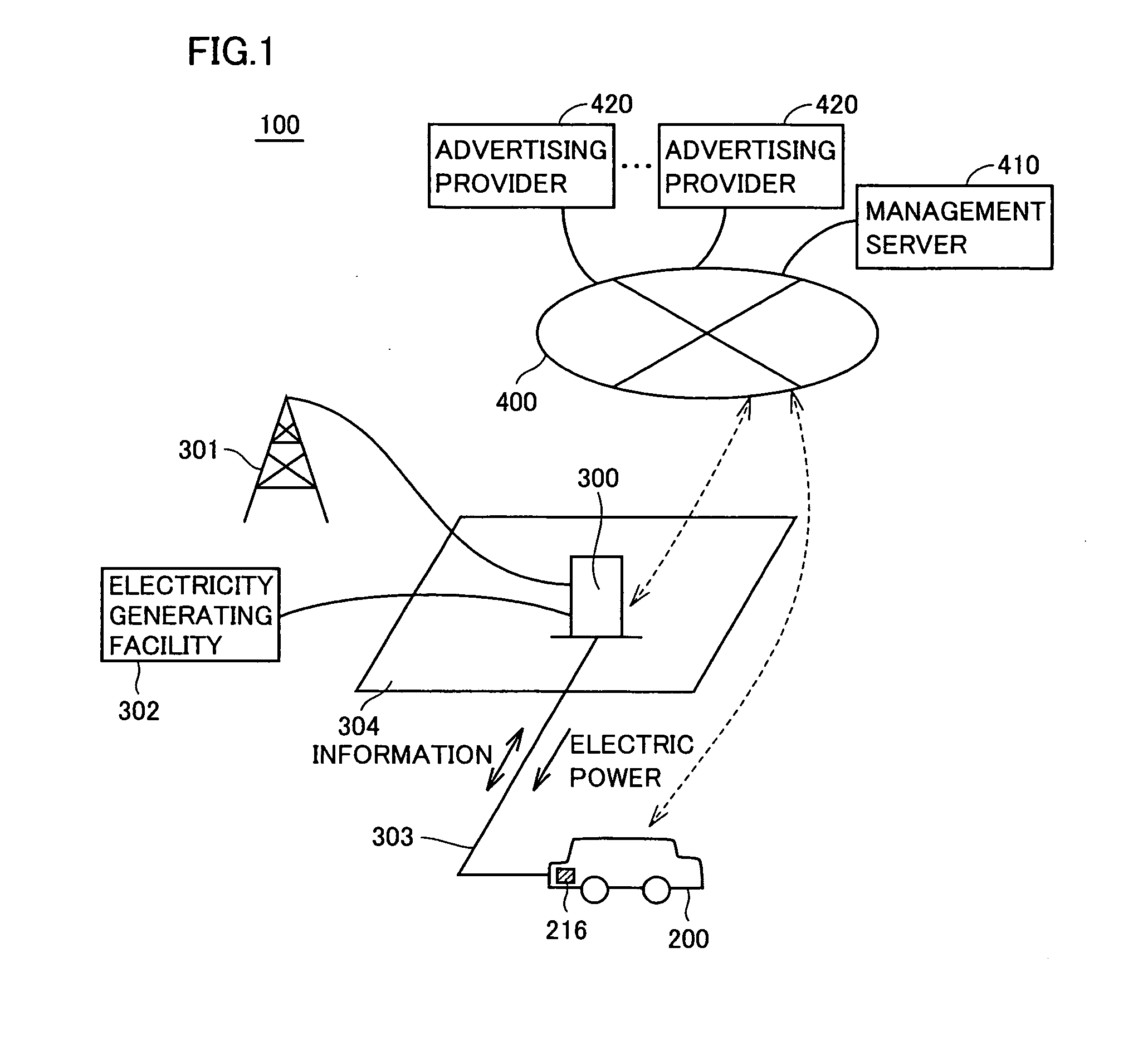
[0031]FIG. 1 is a schematic block diagram showing a configuration example of a charging system of an electric powered vehicle according to the embodiment of the present invention.

[0032]Referring to FIG. 1, charging system 100 according to the embodiment of the present invention includes an electric powered vehicle 200, a charging facility 300, a communication network 400 configured in a wired manner or a wireless manner, a management server 410, and advertising providers 420 each having a device that can access communication network 400.

[0033]Electric powered vehicle 200 includes an electric storage device 216. Electric storage device 216 is configured to be externally charged by being electrically connected to chargi...


PUM


Abstract

An electric storage device of an electric powered vehicle is configured to be chargeable by a charging facility. At the time of external charge by the charging facility, a management server selects advertising information based on information stored inside the electric powered vehicle to be charged and / or information of the charging facility performing the external charge to the electric powered vehicle including a mechanism capable of reproducing the advertising information from an advertising provider, and transmits the selected advertising information. The management server performs billing so that in exchange for the transmission of the advertising information, at least part of a charging power fee is caused to be borne by the advertising provider side to thereby discount an amount borne by an electric powered vehicle user.

Description

[0001]This nonprovisional application is based on Japanese Patent Application No. 2007-312534 filed on Dec. 3, 2007 with the Japan Patent Office, the entire contents of which are hereby incorporated by reference.BACKGROUND OF THE INVENTION[0002]1. Field of the Invention[0003]This invention relates to a charging system of an electric powered vehicle, and more specifically to a charging system of an electric powered vehicle configured to be chargeable by an external charging facility.[0004]2. Description of the Background Art[0005]In recent years, as an eco-friendly vehicle, attentions have been attracted to an electric powered vehicle, such as an electric automobile, a hybrid car, a fuel-cell car and the like, which carries an electric storage device typified by a secondary battery, and as a driving device, has a motor configured so that driving force can be generated by electric power from the electric storage device.[0006]Particularly, with the electric powered vehicle, by construc...

Claims


Application Information

Patent Timeline
IPC IPC(8): G06Q30/00H02J7/00B60L50/16G01C21/26G06Q30/02G06Q30/04G06Q30/06G06Q50/00G06Q50/10H04M3/42H04M11/00
CPCB60L11/123Y02T90/121B60L11/1824B60L11/184B60L2230/16G06Q30/02G06Q30/0265G06Q50/06Y02T10/6217Y02T10/7005Y02T10/7077Y02T10/7088Y02T90/128Y02T90/14Y02T90/163Y02T90/169Y04S30/14B60L2200/26B60L11/14B60L50/61B60L50/16B60L53/30B60L53/64B60L53/305Y02T10/62Y02T10/7072Y02T10/70Y02T90/12Y02T90/167Y02T90/16
Inventor SAKAKIBARA, KATSUMIOKAMURA, YUKIOMORI, KENJIMATSUMOTO, YUTAKASHIBATA, CHITOSEASAKURA, YOSHITAKAKIDO, AKIHIKOISHIKAWA, TETSUHIROYAMADA, HIROYUKIIWASAKI, KIICHI
Owner TOYOTA JIDOSHA KK
Learn More