Data transfer between chips in a multi-chip semiconductor device with an increased data transfer speed
a data transfer speed and semiconductor technology, applied in the direction of pulse technique, transmission monitoring, instruments, etc., can solve the problems of essentially no good lamination type semiconductor device, limited number of wires, and limitations in the miniaturization of semiconductor integrated circuits, so as to prevent a reduction in the amount of data to be transferred
- Summary
- Abstract
- Description
- Claims
- Application Information
AI Technical Summary
Benefits of technology
Problems solved by technology
Method used
Image
Examples
first exemplary embodiment
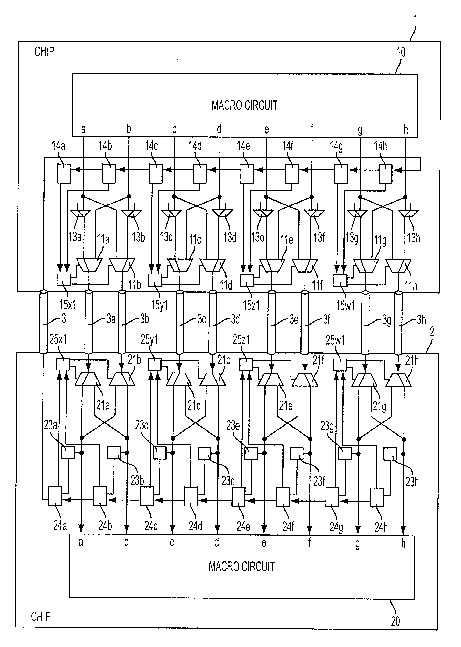
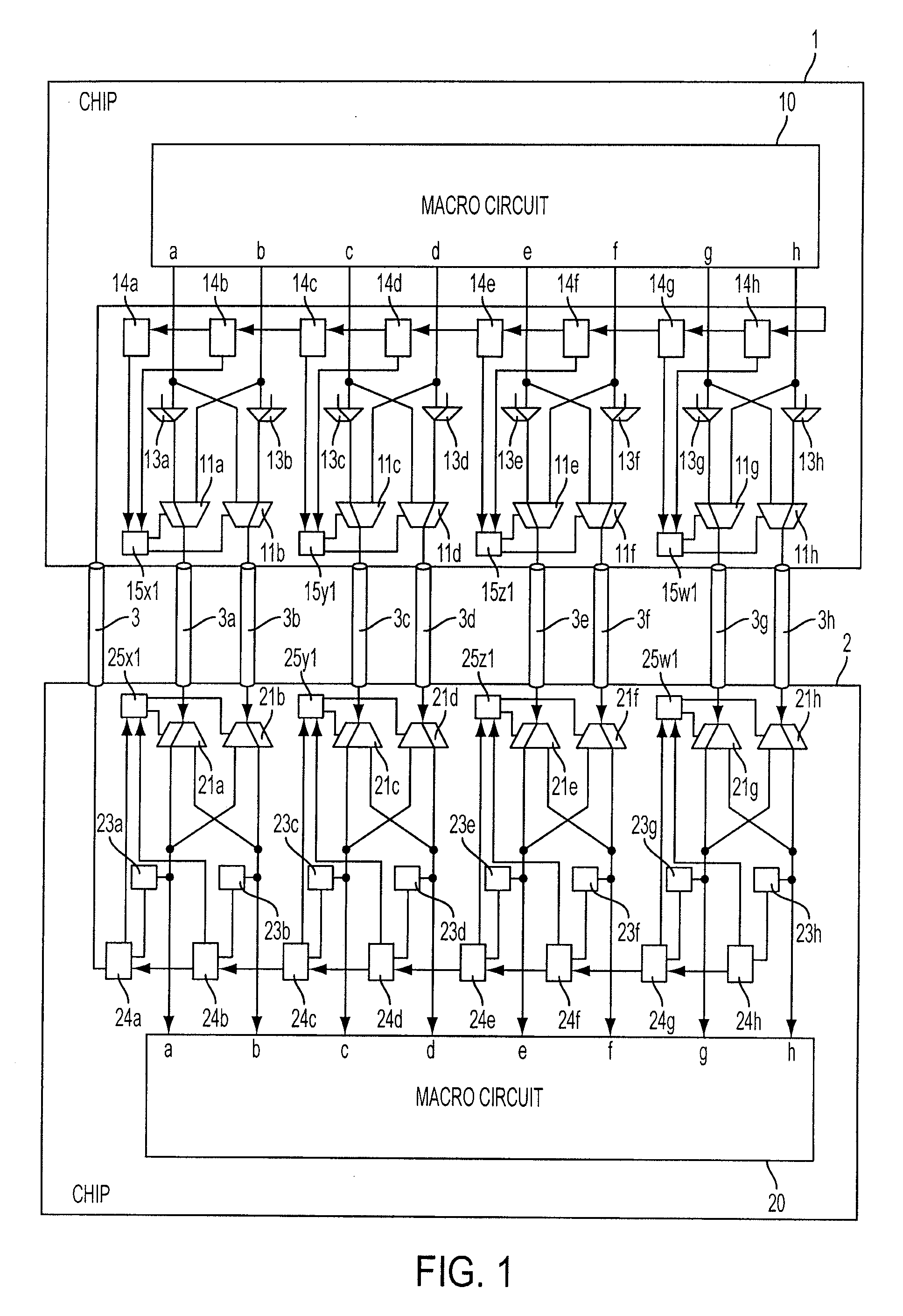
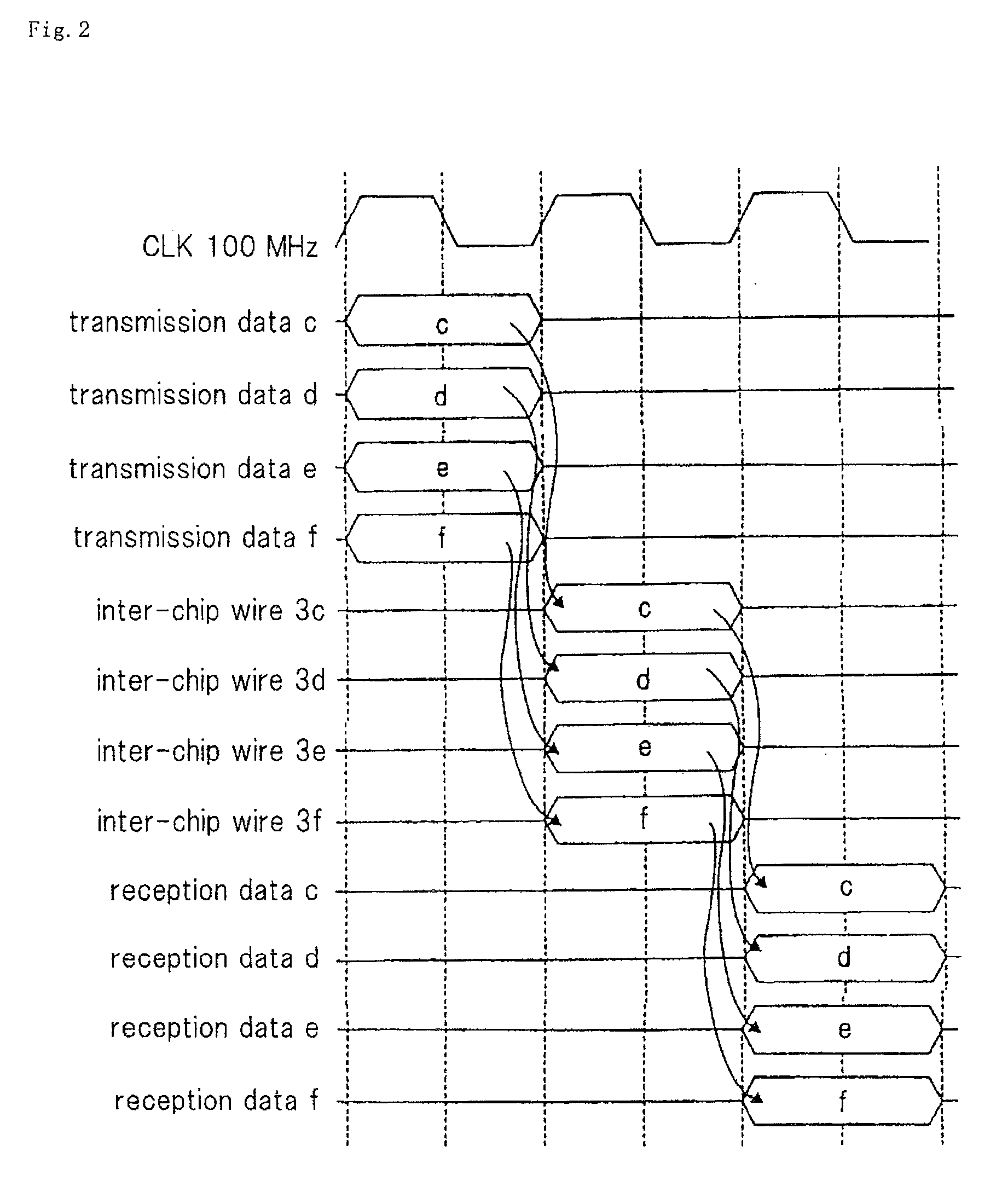
[0037]FIG. 1 is a block diagram of a multi-chip semiconductor device according to a first exemplary embodiment of the present invention. The multi-chip semiconductor device of this exemplary embodiment comprises two semiconductor chips 1, 2; 8 chip wires 3a, 3b, 3c, 3d, 3e, 3f, 3g, and 3h; and test result transmission inter-chip wire 3. In this exemplary embodiment, the clock signal used for data transfer between the chips has a frequency of 100 MHz, and therefore the bandwidth between the chips is 800 Mpbs.
[0038]Chip 1 includes macro circuit 10; transmission buffer circuits 11a 11b, 11c, 11d, 11e, 11f, 11g, and 11h; selectors 13a, 13b, 13c, 13d, 13e, 13f, 13g, and 13h, registers 14a, 14b, 14c, 14d, 14e, 14f, 14g, and 14h; and transfer speed control units 15x1, 15y1, 15z1, and 15w1. Transfer speed control units 15x1 to 15w1 make up a transfer speed control means. Macro circuit 10 outputs 8-bit data comprised of 1-bit data a, b, c, d, e, f, g, and h. Selectors 13a, 13b, 13c, 13d, 13e...
second exemplary embodiment
[0050]FIG. 6 is a block diagram of a multi-chip semiconductor device according to a second exemplary embodiment of the present invention.
[0051]In the first exemplary embodiment, in order to determine whether the connection of each inter-chip wire is good or faulty, a test signal having a certain defined test pattern is transmitted from chip 1 to chip 2, and the connection determination unit in chip 2 determines whether or not a test signal having the test pattern has been received.
[0052]In this exemplary embodiment, the data transfer speeds of transmission buffer circuits 11a, 11b connected with inter-chip wire 3a, 3b to be tested for connection are doubled, and test signal ta to be applied to selector 13a is fixed at a low level, while test signal tb to be applied to selector 13b is fixed at a high level, such that transmission buffer circuits 11a, 11b alternately transfer a test signal having a high level and a test signal having a low level to chip 2 through inter-chip wire 3a, 3...
third exemplary embodiment
[0053]In the first exemplary embodiment, the data transfer speeds of a transmission buffer circuit connected with an inter-chip wire adjacent to an inter-chip wire having a faulty connection is doubled. However, a transmission buffer circuit whose data transfer speed is doubled is not limited to a transmission buffer circuit connected with an inter-chip wire adjacent to an inter-chip wire having a faulty connection.
[0054]In this exemplary embodiment, transmission buffer circuits whose data transfer speed can be doubled are limited to transmission buffer circuit 12a1 connected with first data transfer inter-chip wire 3a and transmission buffer circuit 12e1 connected with fifth data transfer inter-chip wire 3e. If second and seventh inter-chip wires 3b, 3g have faulty connections, data b which would otherwise be sent through second inter-chip wire 3b is transferred through first inter-chip wire 3a, and data g which would otherwise be sent through seventh inter-chip wire 3g is transfer...
PUM
 Abstract
Description
Claims
Application Information
 - R&D
- Intellectual Property
- Life Sciences
- Materials
- Tech Scout
- Unparalleled Data Quality
- Higher Quality Content
- 60% Fewer Hallucinations
Browse by: Latest US Patents, China's latest patents, Technical Efficacy Thesaurus, Application Domain, Technology Topic, Popular Technical Reports.
© 2025 PatSnap. All rights reserved.Legal|Privacy policy|Modern Slavery Act Transparency Statement|Sitemap|About US| Contact US: help@patsnap.com


