
Bifurcate Stent Delivery Catheter

a stent and catheter technology, applied in the field of stent delivery systems, can solve the problems of inability to adjust the clinician, the balloon size for deploying the stent is predetermined, and the technique is not applicable to every case,

Inactive Publication Date: 2009-05-21
MEDTRONIC VASCULAR INC
View PDF11 Cites 88 Cited by
  • Summary
  • Abstract
  • Description
  • Claims
  • Application Information

AI Technical Summary

Benefits of technology

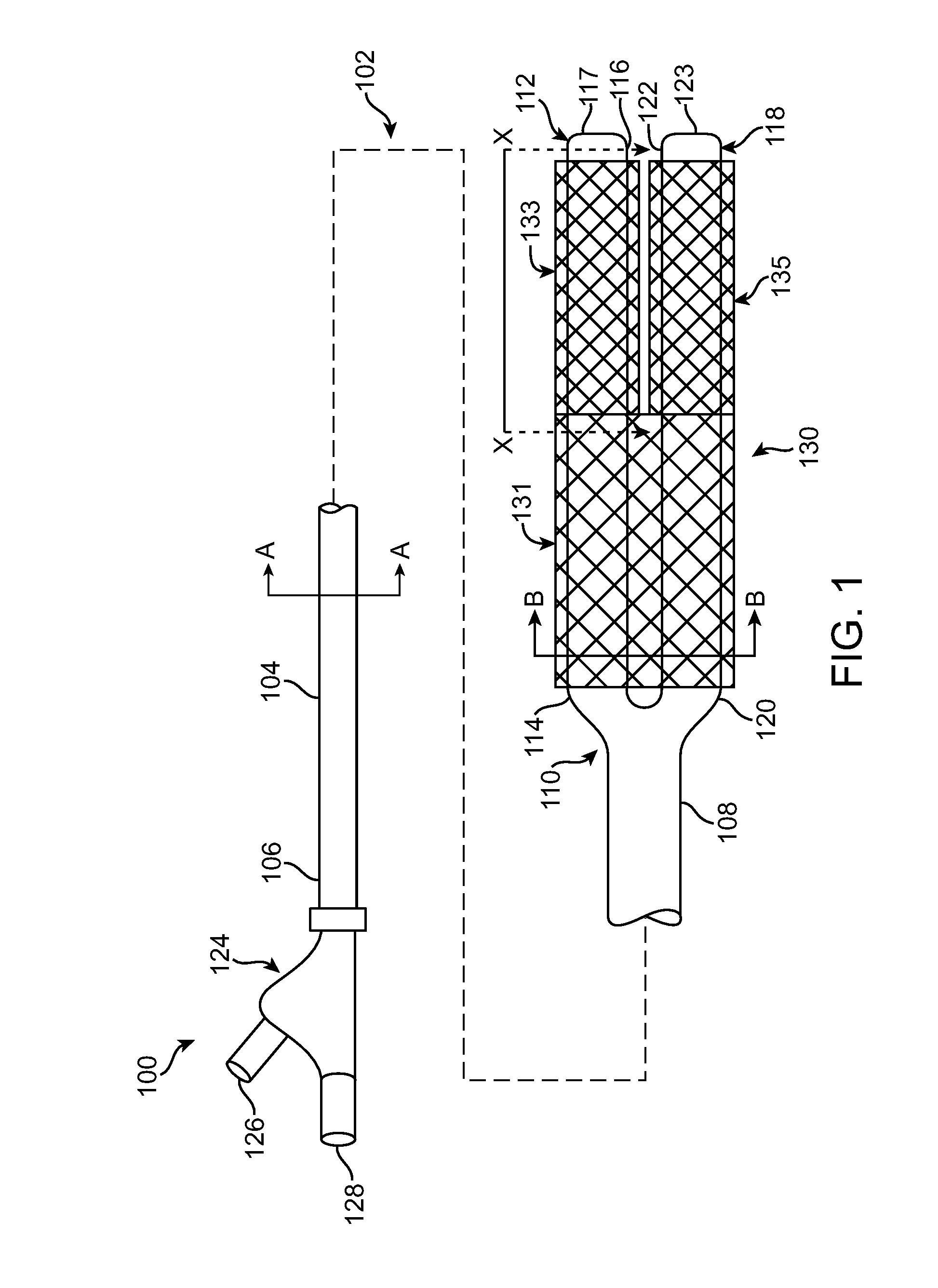
[0027]Embodiments of the present invention are directed to a stent delivery catheter having a stent mounted on a distal portion of a catheter shaft. The distal portion of the catheter shaft is designed to split or otherwise expand in a controlled fashion by a conventional balloon catheter inserted within a lumen of the shaft to thereby permit the expansion or deployment of the stent mounted thereon. Thus, embodiments of the present invention do not have a stent mounted directly on a balloon on the distal end of the stent delivery catheter. Instead, a clinician may select an appropriate balloon size, i.e., an appropriate balloon catheter size, to suit the target body lumen for insertion within the stent delivery catheter in accordance with embodiments of the present invention.
[0028]Although embodiments of the present invention may be applied to any stent delivery system, the present invention is especially advantageous in a bifurcate stent delivery system having a bifurcated stent at the distal end thereof. Since there are no balloon(s) mounted on the distal end of the bifurcate stent delivery catheter, conventional balloon catheters having different size balloons may be used to expand different portions of the bifurcated stent, as will be explained herein.
[0029]An embodiment of the present invention is a bifurcate stent delivery catheter including a proximal shaft and two distal shaft branches having a bifurcated stent mounted thereon, wherein one or more conventional balloon catheters may be advanced within lumens of the bifurcate catheter to deploy the bifurcated stent. Since no balloons are mounted on the bifurcate stent delivery catheter, the clinician may use any combination of balloon sizes for deploying different portions of the bifurcated stent, i.e., the trunk and branches of the stent. As such, the clinician may custom-select appropriate balloon sizes to best treat the bifurcation. Once a conventional balloon catheter is positioned within a distal shaft branch, each of the distal shaft branches of the bifurcate catheter are constructed to split or otherwise expand in a controlled manner in order to allow the bifurcated stent to be expanded or deployed. Conventional balloon catheters that may be used in the present invention includes any type of catheter known in the art, including over-the-wire catheters, rapid-exchange catheters, core wire catheters, and any other appropriate balloon catheters. For example, conventional balloon catheters such as those shown or described in U.S. Pat. Nos. 6,736,827; 6,554,795; 6,500,147; and 5,458,639, which are incorporated by reference herein in their entirety, may be used within the bifurcate stent delivery catheter of the present invention.
[0030]Embodiments of the present invention include various ways to construct the distal shaft branches to expand in a controlled manner such that the bifurcated stent may be expanded or deployed by a conventional balloon catheter advanced through the lumen of the distal shaft branches. In one embodiment, the first and second distal shaft branches each have an area of weakness that splits open in response to inflation of a balloon of the conventional balloon catheter. The area of weakness may be a perforation, a slit, a slot, a groove, or a connector such as an adhesive which is breakable by the inflation of a balloon. In another embodiment, the distal shaft branches are constructed of a coiled tube that unrolls in response to inflation of a balloon of the conventional balloon catheter. In yet another embodiment, the distal shaft branches are constructed out of an elastomer material that expands in response to inflation of a balloon of the conventional balloon catheter.
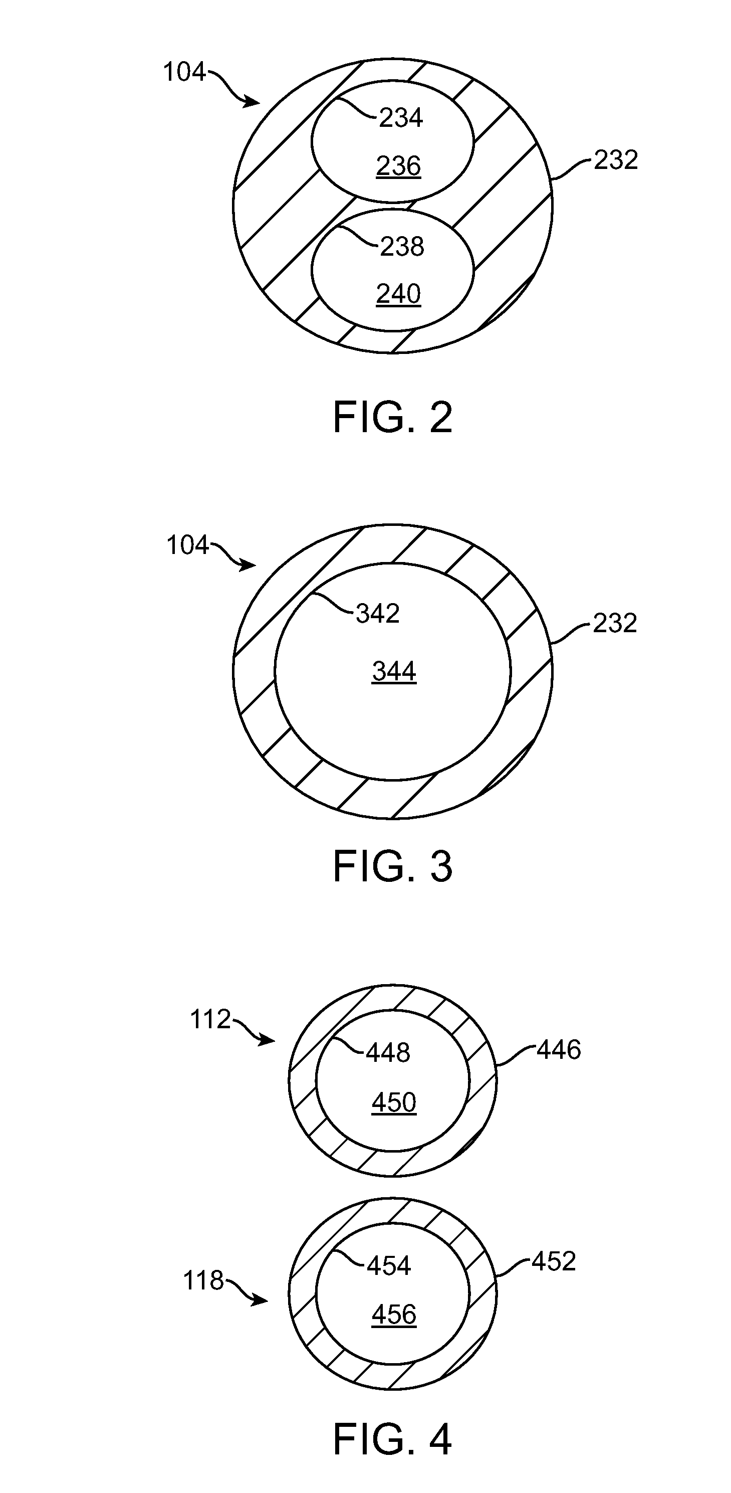
[0031]The distal shaft branches typically are constructed out of a more flexible material than the proximal shaft, and typically have a smaller outer diameter than the proximal shaft. Each distal shaft branch includes one lumen there through for accommodating insertion of one conventional balloon catheter.

Problems solved by technology

Although systems and techniques exist that work well in many cases, no technique is applicable to every case.
Since the stent is typically mounted on the balloon, the balloon size for deploying the stent is predetermined and cannot be adjusted by the clinician in vivo.

Method used


Image

  • Bifurcate Stent Delivery Catheter
  • Bifurcate Stent Delivery Catheter
  • Bifurcate Stent Delivery Catheter

Examples


Embodiment Construction

[0025]Specific embodiments of the present invention are now described with reference to the figures, wherein like reference numbers indicate identical or functionally similar elements. The terms “distal” and “proximal” are used in the following description with respect to a position or direction relative to the treating clinician. “Distal” or “distally” are a position distant from or in a direction away from the clinician. “Proximal” and “proximally” are a position near or in a direction toward the clinician.

[0026]The following detailed description is merely exemplary in nature and is not intended to limit the invention or the application and uses of the invention. Although the description of the invention is in the context of treatment of blood vessels such as the coronary, carotid and renal arteries, the invention may also be used in any other body passageways where it is deemed useful. Furthermore, there is no intention to be bound by any expressed or implied theory presented in ...


PUM


Abstract

A bifurcate stent delivery catheter is disclosed that includes a proximal shaft and two distal shaft branches having a bifurcated stent mounted thereon, wherein one or more conventional balloon catheters may be advanced within lumens of the bifurcate catheter to deploy the bifurcated stent. Since no balloons are mounted on the bifurcate catheter, the clinician may use any combination of balloon sizes for deploying various portions of the bifurcated stent and thus custom-select appropriate balloon sizes to best treat the bifurcation. Once a conventional balloon catheter is positioned within a distal shaft branch of the bifurcate stent delivery catheter, each of the distal shaft branches of the bifurcate catheter are constructed to split or otherwise expand in a controlled manner upon expansion of the balloon catheter in order to allow the bifurcated stent to be expanded or deployed.

Description

FIELD OF THE INVENTION[0001]The present invention relates in general to stent delivery systems employed in the treatment of vascular disease. More particularly, the present invention relates to a stent delivery system that has a bifurcated stent attached at the distal end thereof for treatment of vascular disease in arterial bifurcations.BACKGROUND OF THE INVENTION[0002]Balloon angioplasty employs balloon tipped catheters to expand the walls of narrowed vessels and to deploy endoluminal prostheses to maintain lumen patency. Although systems and techniques exist that work well in many cases, no technique is applicable to every case. For example, special methods exist for dilating lesions that occur in branched or bifurcated vessels. A bifurcation is an area of the vasculature where a main vessel is bifurcated into two or more branch vessels. It is not uncommon for stenotic lesions to form in such bifurcations. The stenotic lesions can affect only one of the vessels, i.e., either of t...

Claims


Application Information

Patent Timeline
Patent Type & Authority Applications(United States)
IPC IPC(8): A61F2/84A61F2/82A61F2/06
CPCA61F2/954A61F2002/065A61F2/97A61F2/958
Inventor DUFFY, NIALLMATHESON, IAN
Owner MEDTRONIC VASCULAR INC
Learn More