
Display device

a display device and display technology, applied in the field of display devices, can solve the problems of inability to achieve sufficient video display performance with fixed switching on (or off) timing, and the backlight cannot be intermittently lighted, so as to achieve the effect of reducing the degree of moving image blur, good display quality, and reducing the degree of blurring

Inactive Publication Date: 2009-05-14
JAPAN DISPLAY INC +1
View PDF10 Cites 69 Cited by
  • Summary
  • Abstract
  • Description
  • Claims
  • Application Information

AI Technical Summary

Benefits of technology

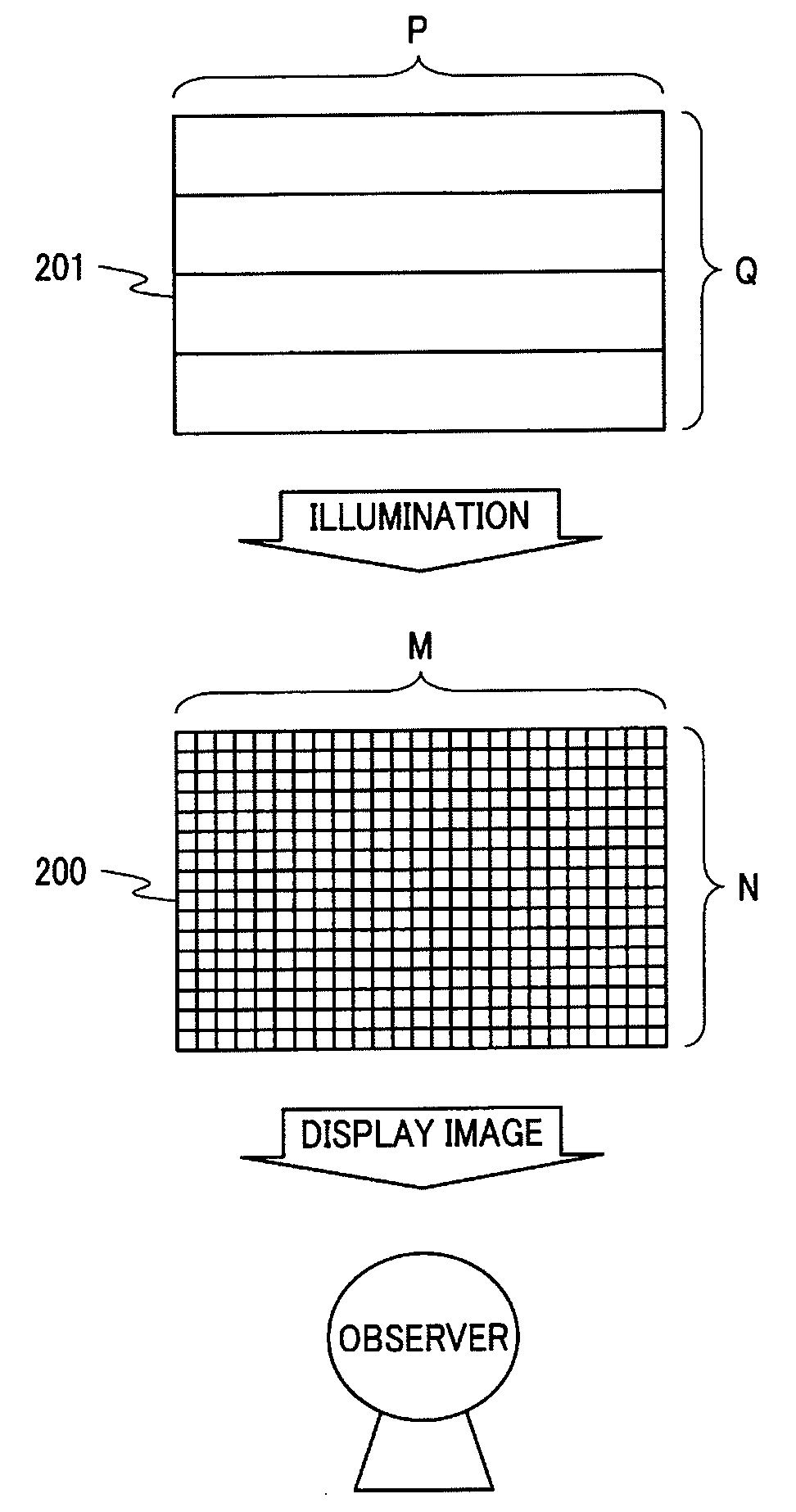
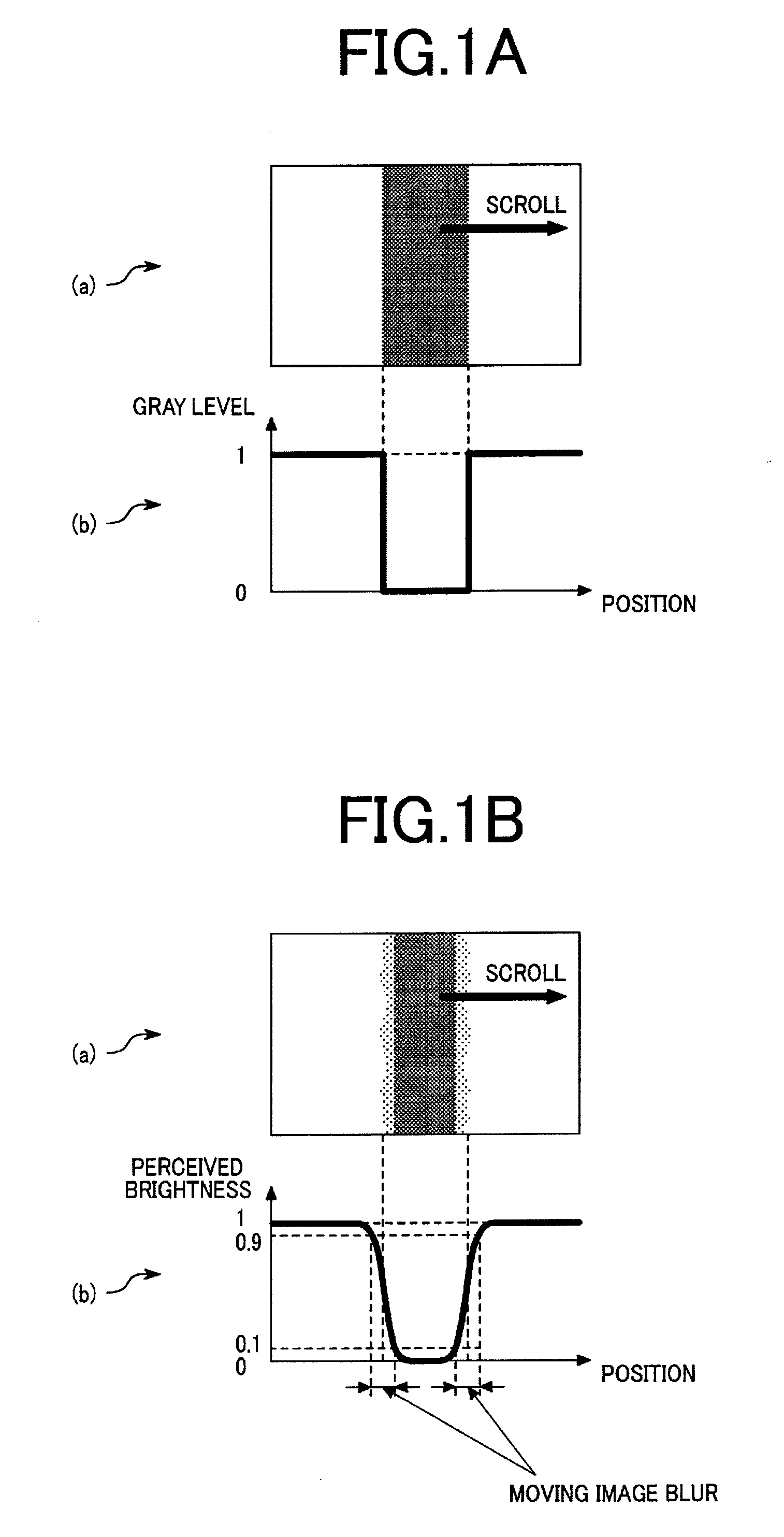
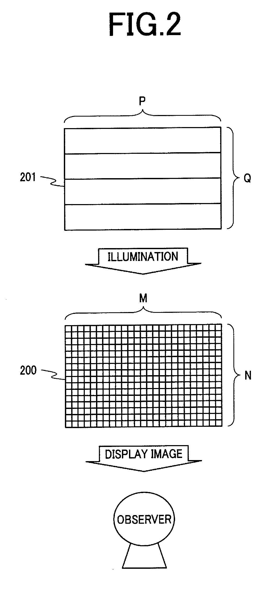
[0014]In accordance with the present invention, the display characteristics of an impulse-type display device can be produced and good display quality with little moving image blur can be obtained in a hold-type display device by intermittently lighting the backlight. Furthermore, in accordance with the present invention, a degree of occurrence of moving image blur can be constantly minimized and good display quality can be maintained regardless of the length of the lighting period of the backlight, even in cases in which the lighting period of the backlight is varied in accordance with the content of the image data or the like for the purpose of improving the contrast of an image as well as making other enhancements to image quality in the above mentioned display device.
[0015]In backlight intermittent lighting, the effect of improving moving image blur increases as the lighting period of the backlight is reduced. In other words, in accordance with the present invention, a highly convenient display device having a function for varying the lighting period of the backlight can be provided in which, e.g., an operation mode with the short lighting period of the backlight, dark screen and low moving image blur and an operation mode with long lighting period of the backlight, considerable moving image blur and bright screen instead are provided, and the operation modes can be selected in accordance with the preferences of the user of the display device.

Problems solved by technology

Accordingly, there exists a problem that when the lighting period of the black light is varied in accordance with the content or the like of the video data, the backlight cannot be intermittently lighted with optimal switching on (or off) timing, and sufficient video display performance may not be obtained with fixed switching on (or off) timing.

Method used


Image

  • Display device
  • Display device
  • Display device

Examples


example 1

[0070]FIG. 8 is a block diagram of a display device for describing example 1 of the present invention. The display device is, e.g., a display device for a TV receiver, a PC (personal computer), mobile phone, and other information apparatuses, and is a typical liquid crystal display device provided with a function for receiving and displaying various image data as input.

[0071]The display device is composed of a display panel 8010, a panel control part 8020, an image characteristic extraction part 8030, an image-coordinated brightness adjusting part 8040, an intermittent lighting brightness adjustment part 8050, a lighting ratio calculation part 8060, a phase calculating part 8070, a backlight control signal generation part 8080, and a backlight 8090. The display device receives a synchronization signal 8001 and image data 8002 as input from an external device (not shown). The synchronization signal 8001 is composed of, e.g., a vertical synchronization signal for specifying a single f...

example 2

[0090]The configuration of the display device of example 2 of the present invention will be described next with reference to FIGS. 9 and 10.

[0091]FIG. 10 is a configuration example of the display device of example 2 of the present invention. The display device of example 2 has the configuration of example 1 shown in FIG. 8 and is additionally provided with an internally set brightness adjustment signal 9100. Other points are substantially the same as the configuration shown in FIG. 8, and a description is therefore omitted. In FIG. 9, the internally set brightness adjustment signal 9100 outputs internally set brightness adjustment information 9101 for adjusting the brightness specified in advance inside the display device. For example, a polychromatic light source other than a white light source can be used as a backlight 9090. For example, when the light source of the backlight 9090 is an LED, an LED having three primary colors red, green, and blue can be used in place of using a w...

example 3

[0102]The configuration of the display device of example 3 of the present invention will be described next with reference to FIG. 12.

[0103]FIG. 12 is a block diagram of the display device of example 3 of the present invention. Example 3 has a data conversion part 11110 additionally provided to the configuration example shown in FIG. 10, and is different on the point of having a configuration in which an externally set brightness signal 11003 is inputted to the data conversion part 11110 in addition to the lighting ratio calculation part 11060. Other points are substantially the same as the configuration shown in FIG. 10 and a description is therefore omitted.

[0104]The data conversion part 11110 is provided with a function for performing various data conversions on the image data 11002 on the basis of the externally set brightness signal 11003 and the characteristic value 11031 of the image data extracted by the image characteristic extraction part 11030. Reference numeral 11112 show...


PUM


Abstract

There is provided a display device capable of delivering adequate video display performance even when a lighting period of a backlight is varied in accordance with the content or the like of image data. The device has circuits (8050, 8060) for varying a lighting period of a backlight (8090) for illuminating a display panel (8010) in accordance with image data (8002), setting information (8003), and the like from an external device; and circuits (8070, 8080) for adjusting the timing of start (and turning off) of lighting of the backlight in accordance with the length of the lighting period.

Description

CROSS-REFERENCE TO RELATED APPLICATION[0001]The present application claims priority from Japanese applications JP 2007-285719 filed on Nov. 2, 2007 and JP 2008-117061 filed on Apr. 28, 2008, the content of which is hereby incorporated by reference into this application.BACKGROUND OF THE INVENTION[0002]1. Field of the Invention[0003]The present invention relates to a display device provided with a display panel for displaying an image by adjusting the transmissivity of light from a light source.[0004]2. Description of the Related Art[0005]Display devices can be largely classified into impulse-type display devices and hold-type display devices from the very viewpoint of characteristics of displaying moving images. An impulse-type display device is a device, such as a cathode-ray tube for example, in which the brightness of scanned pixels gets greater only within the period in which the pixels are being scanned, and in which the brightness is reduced immediately after scanning. A hold-...

Claims


Application Information

Patent Timeline
Patent Type & Authority Applications(United States)
IPC IPC(8): G09G5/10G09G3/36
CPCG09G3/3413G09G2360/16G09G3/3611G09G2310/024G09G2310/08G09G2320/0238G09G2320/0242G09G2320/0261G09G2320/0271G09G2320/0606G09G2320/0633G09G2320/064G09G2320/0646G09G2320/103G09G2330/021G09G2330/025G09G2330/06G09G2360/144G09G3/3426
Inventor MARUYAMA, JUNICHIOOISHI, YOSHIHISAOKADA, YUKISHOJI, TAKASHIONO, KIKUOIMAJO, IKUKOBABA, MASASHI
Owner JAPAN DISPLAY INC
Learn More