
Microbolometer infrared security sensor

a microbolometer and infrared technology, applied in the field of infrared security sensors, can solve the problems of inability to imaging passive infrared (pir) sensors used widely in security systems, and inability to achieve wide-scale use. , to achieve the effect of reducing johnson and 1/f noise, increasing pixel bias voltage, and improving performan

Inactive Publication Date: 2009-05-14
IR SENSORS PTY LTD
View PDF15 Cites 22 Cited by
  • Summary
  • Abstract
  • Description
  • Claims
  • Application Information

AI Technical Summary

Benefits of technology

"The invention is an infrared security sensor that includes a focal plane array with a plurality of pixels, each pixel including a mosaic of electrically interconnected sub-pixels. The sensor has a higher performance and extended capability compared to existing PIR sensors. The sensor can detect and analyze the number, size, shape, speed, and direction of movement of detected targets and can also display the detected image. The sensor includes a matrix of sub-pixels microbolometer detectors, each pixel in the focal plane array comprising a number of sub-pixels. The sensor provides for increased pixel bias voltage, reduced Johnson and 1 / f noise, and use of a microbolometer material with higher temperature coefficient of resistance. The optical system includes a single or multi-element Fresnel lens or a germanium or chalcogenide glass lens with aspheric or binary surface geometry. The sensor can detect and recognize targets, as well as detecting developing fire or overheating electrical appliances. The output display can be monitored locally or remotely via telephone line or radio link to a monitor base. The invention also includes a method of detecting an infrared signal using the apparatus described in the patent."

Problems solved by technology

Current sensors are either too expensive for wide-scale use in this market segment, or have inadequate performance.
The common passive infrared (PIR) sensor used widely in security systems is incapable of imaging and produces a simple hot-spot detection of a moving target.
These sensors cannot detect stationary targets, or discriminate clearly between a human and other target, and are subject to false alarms.
In particular there are no known affordable IR security sensors that are able to detect stationary targets or targets where temperature changes relatively slowly.

Method used


Image

  • Microbolometer infrared security sensor
  • Microbolometer infrared security sensor
  • Microbolometer infrared security sensor

Examples


Embodiment Construction

[0033]The following detailed description of the invention refers to the accompanying drawings. Although the description includes exemplary embodiments, other embodiments are possible, and changes may be made to the embodiments described without departing from the spirit and scope of the invention. Wherever possible, the same reference numbers will be used throughout the drawings and the following description to refer to the same and like parts.

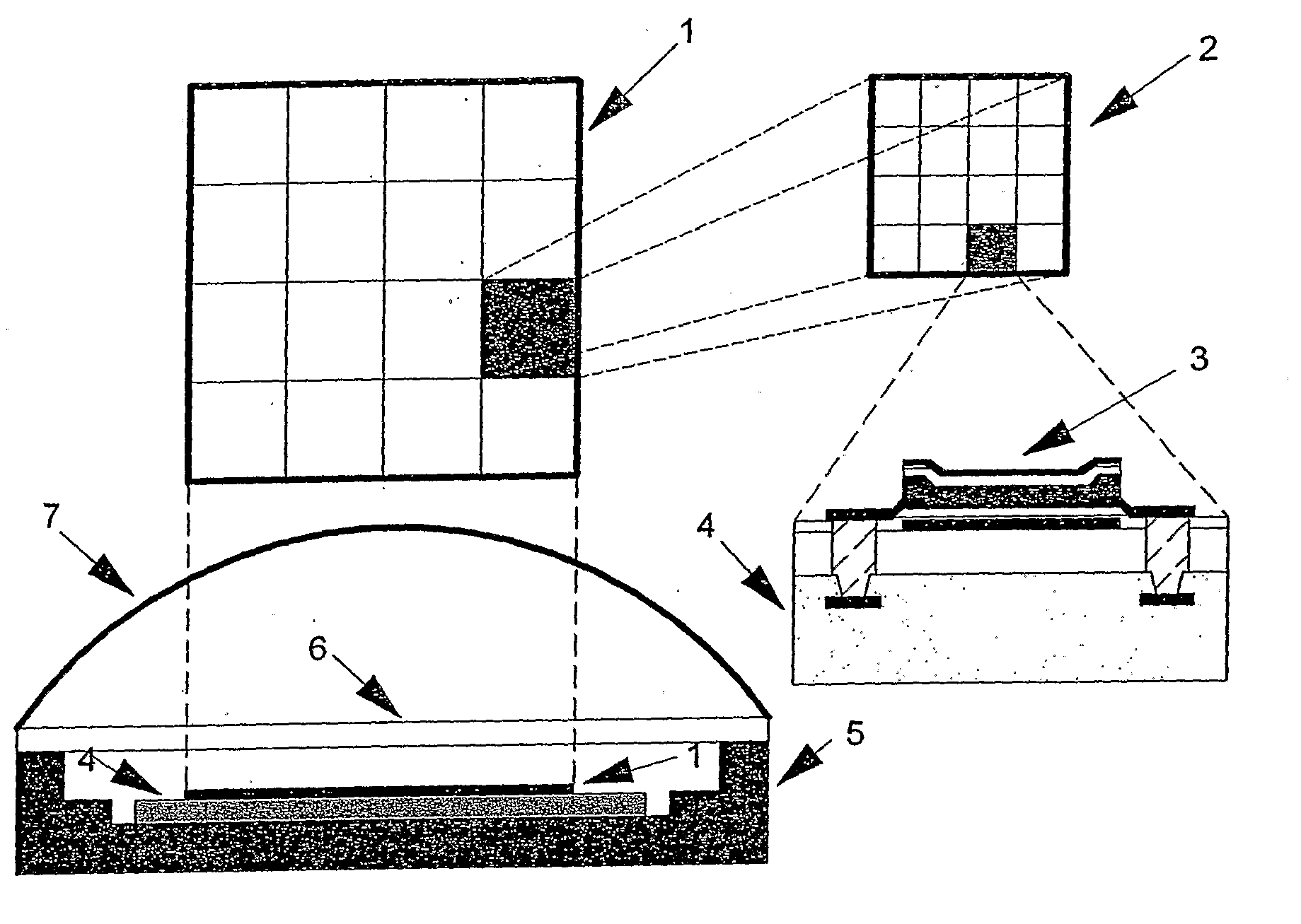
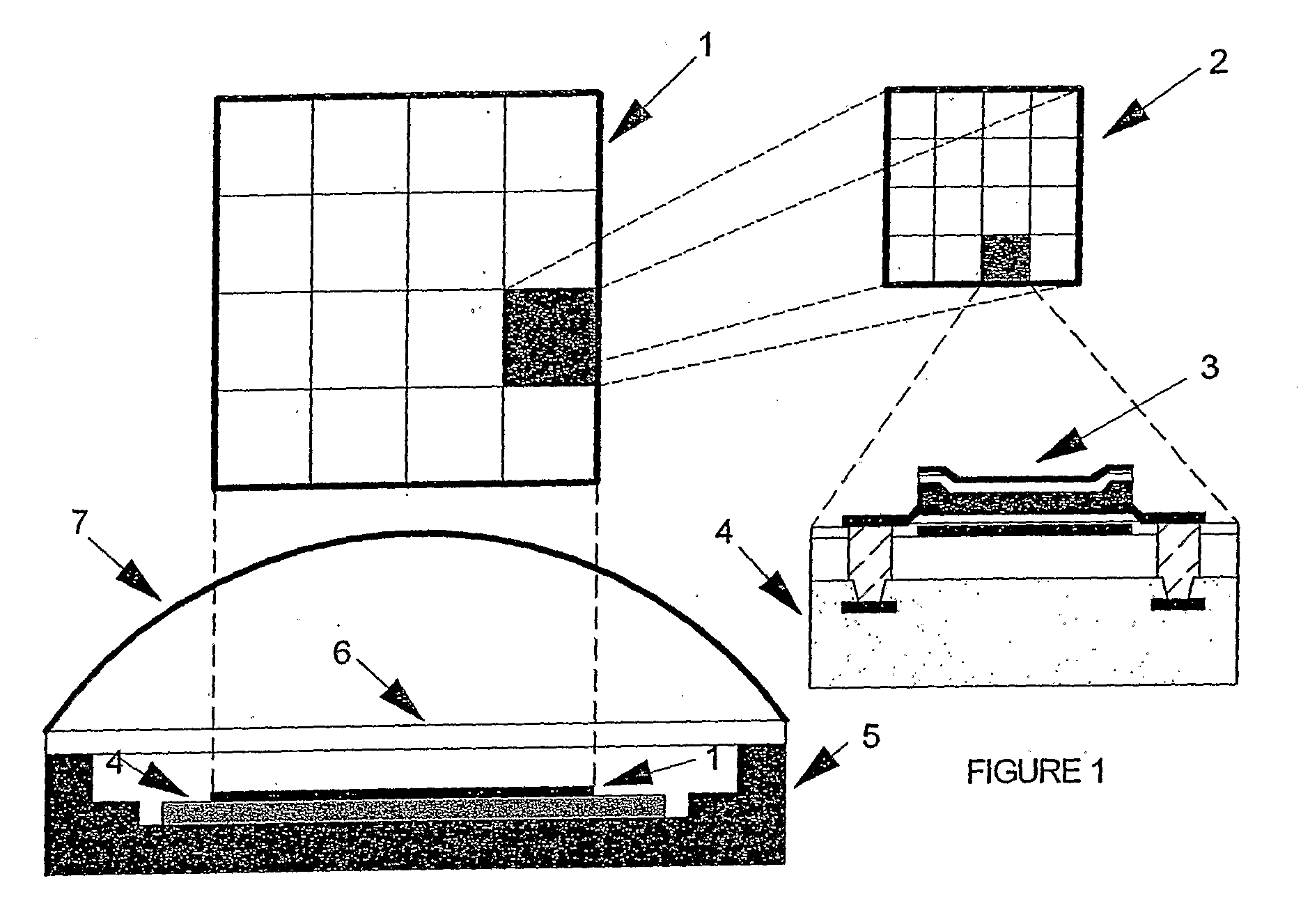
[0034]Illustrated in FIG. 1 is a MP-FPA 1 in both plan and cross-section comprising an array of 4×4 imaging pixels. Each pixel comprises an array of sub-pixels 2, each sub-pixel 2 being a functional IR detector 3, illustrated in cross-section. In this example there are 4×4 sub-pixels.

[0035]The MF-FPA is formed on and integrated with a ROIC 4 and mounted in package 5. The package 5 has an IR transmitting window 6 and is coupled to an IR lens 7. In some instances, the lens 7 may fit directly to the package 5 so that the window 6 is not required....


PUM


Abstract

An infrared sensor, comprising a focal plane array (FPA) of resistance microbolometer infrared detectors connected in such a manner to produce different pixel formats to meet specific detection requirements. Typically each imaging pixel may be a mosaic comprising a number of sub-pixels connected in parallel (although other configurations are possible), resulting in enhanced performance and ease of manufacture by micro-fabrication methods. The FPA may be integrated with a readout microcircuit on the same substrate so that with appropriate signal processing one is capable of forming an image of the field of view of interest, facilitating target recognition and very low false alarm rate.

Description

FIELD OF THE INVENTION[0001]The present invention relates to an infrared security sensor, including a focal plane array (FPA) of resistance microbolometer infrared detectors connected in such a manner to produce different pixel formats to meet specific detection requirements. The FPA may be integrated with a readout microcircuit (ROIC) on the same substrate so that with appropriate signal processing and low cost lens one is capable of forming an image of the field of view of interest, facilitating target recognition and very low false alarm rate.[0002]Typically each imaging pixel may be a mosaic comprising a number of sub-pixels connected in parallel (although other configurations are possible), resulting in enhanced performance and ease of manufacture by micro-fabrication methods. The arrangement of such as mosaic pixel focal plane array will hereinafter be referred to as a MP-FPA.[0003]The present invention also further relates to a method of formulating such an infrared sensor ut...

Claims


Application Information

Patent Timeline
Patent Type & Authority Applications(United States)
IPC IPC(8): G01J5/00
CPCG01J5/20G01J5/22G08B13/193H04N5/33H01L27/14618H01L27/14625H01L27/14669G08B17/12H01L2924/0002H04N23/23H01L2924/00
Inventor LIDDIARD, KEVIN
Owner IR SENSORS PTY LTD
Learn More