
Firehose Coupling Exit Indicator

a technology of direction indicators and firehoses, applied in the direction of hose connections, couplings, instruments, etc., can solve the problems of minimize the chances of safe escape, and inability to detect the direction of firefighters, etc., to achieve enhanced visual indication and increase the thickness

Active Publication Date: 2009-05-14
LIFECROWN LLC
View PDF28 Cites 30 Cited by
  • Summary
  • Abstract
  • Description
  • Claims
  • Application Information

AI Technical Summary

Benefits of technology

[0015]Provide a direction indicating device at the coupling between firehose sections that is inexpensive to manufacture, yet provides a reliable indicator toward the hose source for a firefighter in a dark, smoke-filled building;
[0016]Provide an inexpensive direction indicating device that can be attached to couplings of existing firehoses so that entire new couplings need not be purchased;
[0017]Provide a direction indicating device at the coupling between firehose sections that provides a reliable tactile indicator of the firehose source direction for a firefighter wearing the thick gloves of a firefighting ensemble in a dark, smoke-filled building;
[0018]Provide a direction indicating device at the coupling between firehose sections that provides a reliable visual indicator toward the hose source for a firefighter in a dark, smoke-filled building;
[0020]Provide a direction indicating device at the coupling between firehose sections that is arranged and designed to prevent the unintended removal of the device while connecting and disconnecting the coupling.
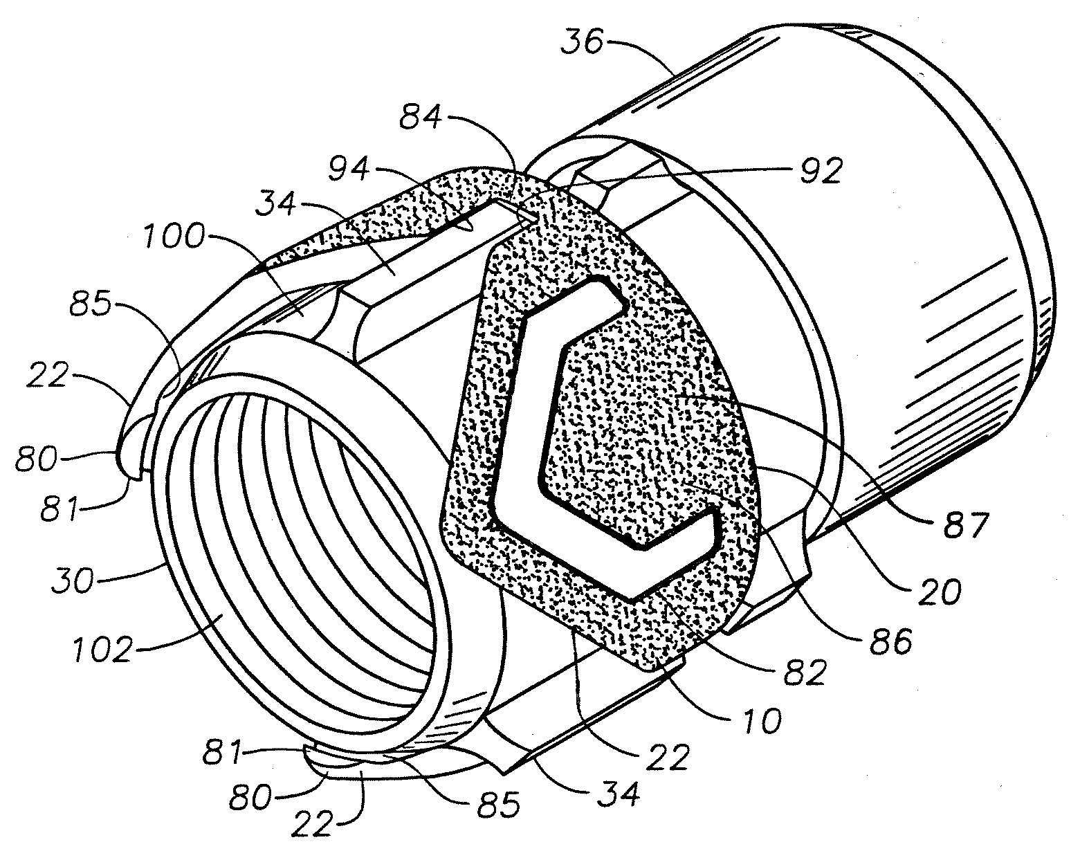
[0022]The objects identified above, along with other advantages and features, are preferably embodied in an annular direction indicating device which fits over the male threads of a male coupling of a firehose. The direction indicating device has integral indicating fingers which point backward from the coupling toward the hose source. Such fingers fit in the gaps of the lugs of the male coupling. The fingers preferably are shaped like arrowheads and have deep arrow-shaped relief grooves or raised ridges on the outer faces so that a firefighter can easily determine by feel the direction to which they are pointing. The fingers of the device may increase in thickness toward the pointed end and may extend longitudinally well beyond the male hose coupler end to provide a further tactile indicator of the direction toward the firehose source. The device also preferably has a lip or rim on the inwardly facing surface of each finger positioned at or near the tip, which prevents the device from being unintentionally removed from the male coupling while connecting or disconnecting the male and female couplings. Alternatively, or additionally, the fingers may be sloped or curved inwardly toward the male coupling and / or firehose section such that the fingers of the device must be spread apart from each other in order to remove the device from the male coupling. Inwardly sloped or curved fingers, especially at their pointed ends or tips, also assist in preventing the fingers from becoming entangled with foreign objects or debris during firehose use. The direction indicating device is preferably made of a strong engineering thermoplastic, polycarbonate, and / or rubber material which includes luminescent, phosphorescent, fluorescent and / or reflective particles therein for enhanced visual indication of the direction towards safety. The raised or recessed arrowhead-shaped indicia may have a coating which is in sharp contrast to the outward-facing surfaces of the fingers for additional visual recognition.

Problems solved by technology

However, under the stresses and pressures of a fire emergency, a firefighter may lose his / her sense of direction, and upon finding a firehose may be unable to conclude which direction leads to the outside water source and which direction leads to the nozzle.
As explained in U.S. Pat. No. 4,884,000, innumerable other problems can arise which further minimize the chances of a safe escape.
Problems are inherent in a device which must be attached by encircling a firehose.
Such lugs are costly to manufacture and require large capital expenditures to provide new coupling sets to equip many firehoses for a large city fire department.

Method used


Image

  • Firehose Coupling Exit Indicator
  • Firehose Coupling Exit Indicator
  • Firehose Coupling Exit Indicator

Examples


Embodiment Construction

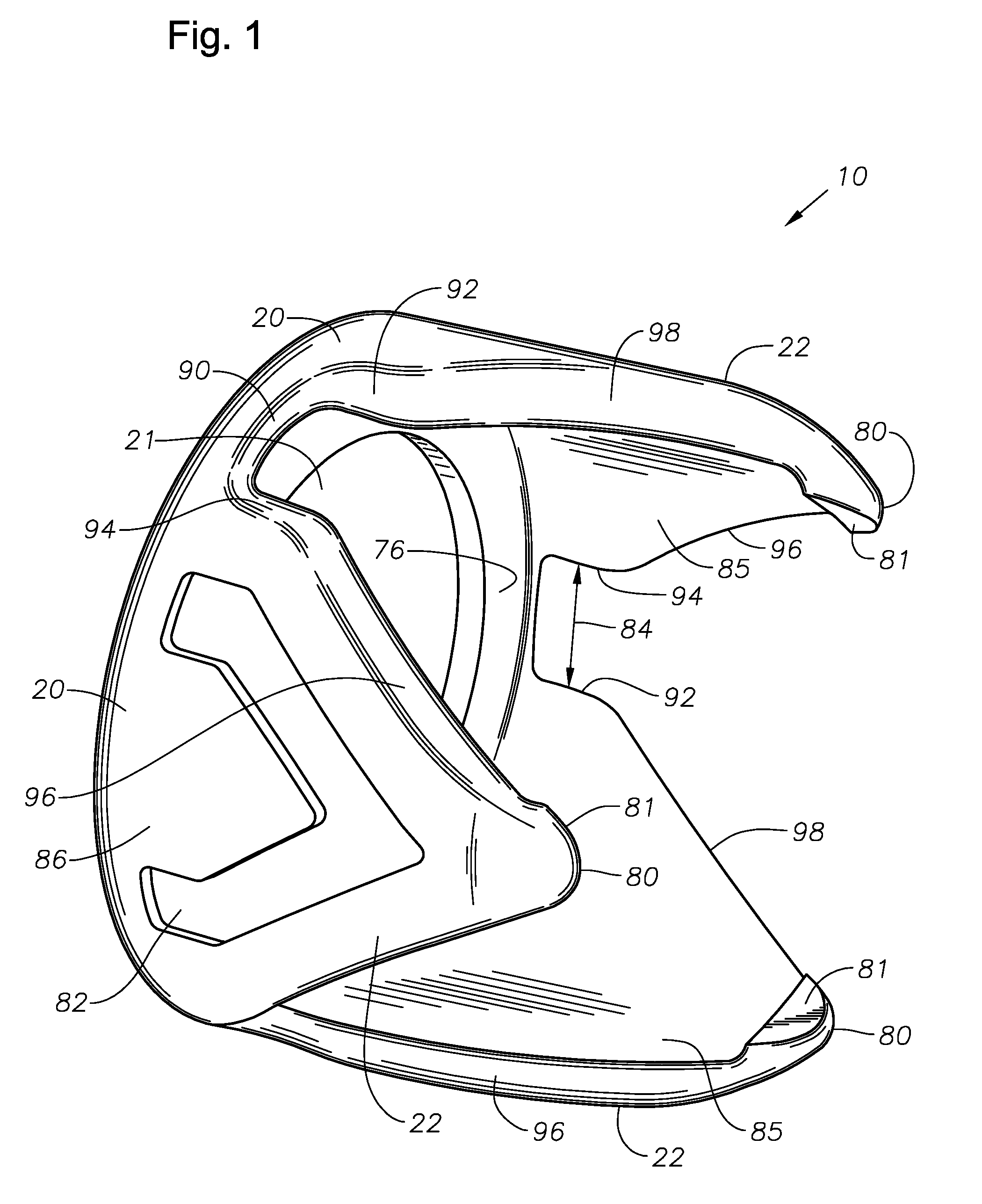
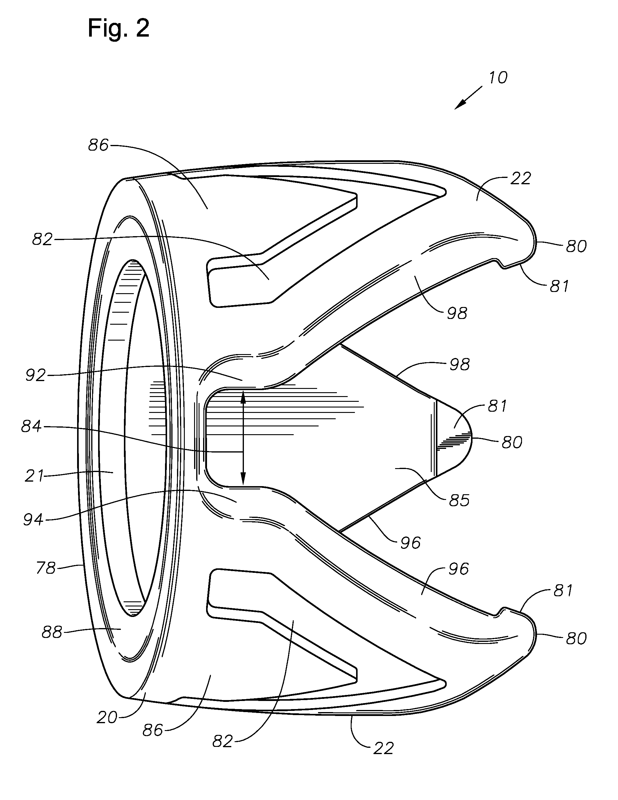
[0030]FIGS. 1 and 2 illustrate the firehose direction indicating device 10 according to a preferred implementation of the invention. The indicating device 10 includes a generally planar annular body 20 with aperture 21. Referring to FIG. 1, the annular body has a first face 76 from which a plurality of arrowhead-shaped circumferential fingers 22 extend perpendicularly in a common direction from the plane of body 20. FIGS. 1 and 2 show three fingers 22, but a different number of fingers may be suitable. Preferably, fingers 22 are integral with body 20 and are circumferentially spaced about body 20 so as to define an equal number of narrow slots 84.

[0031]Ideally, each finger 22 has an irregular pentagon shape defined by a first, base edge 90 (formed by a circumferential portion of body 20), second and third side edges 92, 94 which extend perpendicularly to the plane of body 20, and fourth and fifth edges 96, 98 which close the pentagon and generally form an arrowhead shape. The tips 8...


PUM


Abstract

A direction indicator device captured between couplers of ends of firehose sections that point to the source of the firehose and to safety. The direction indicator device includes a gasket-like annular body which fits over the male threads of the male coupler and is captured between annular ends of the abutting male and female coupler bodies. Direction pointing fingers, integral with the annular body, point toward the hose section to which the male coupler is attached and are angularly oriented to fit between longitudinal lugs of the male coupler. A lip is provided on an inwardly facing surface at each finger tip to hinder removal and to prevent inadvertent removal of the device from the male coupler body.

Description

BACKGROUND OF THE INVENTION[0001]1. Field of the Invention[0002]This invention relates generally to direction indicators associated with a firehose to assist a firefighter in safe egress from a smoke-filled building using the firehose.[0003]2. Description of the Prior Art[0004]A primary concern of fire fighting personnel is that of becoming lost in a burning or smoke-filled structure where the firefighter does not know the direction to the outside. Firefighters are commonly taught to follow the firehose lines, knowing that the firehose connects from an outside source of water to the water spraying nozzle. However, under the stresses and pressures of a fire emergency, a firefighter may lose his / her sense of direction, and upon finding a firehose may be unable to conclude which direction leads to the outside water source and which direction leads to the nozzle. As explained in U.S. Pat. No. 4,884,000, innumerable other problems can arise which further minimize the chances of a safe es...

Claims


Application Information

Patent Timeline
IPC IPC(8): G01D13/22
CPCA62B3/00F16L2201/60A62C33/00Y10S116/17
Inventor TAMEZ, JR., ISIDRO
Owner LIFECROWN LLC
Learn More