
Food Article Feed Apparatus for a Food Article Slicing Machine

a technology of food article and feed apparatus, which is applied in the direction of sawing apparatus, metal working apparatus, manufacturing tools, etc., can solve the problems that the reload cycle time can be a significant limitation to optimum production efficiency, and achieve the effect of optimizing the weight control and yield of each food articl

Active Publication Date: 2009-05-14
PROVISUR TECHNOLOGIES INC
View PDF101 Cites 78 Cited by
  • Summary
  • Abstract
  • Description
  • Claims
  • Application Information

AI Technical Summary

Benefits of technology

[0009]The invention provides a mechanism and method for slicing multiple food articles with independency of feed rate and the ability to weigh each product group from each food article respectively to achieve optimal weight control and yield of each food article.
[0010]The present invention provides a high speed slicing apparatus and a weighing and classifying conveyor combination that provides plural advantages in productivity, food hygiene, and operation.
[0011]The combination provides food hygiene advantages by use of unibody construction with minimal penetrations, double sealed door closures, self draining angled surfaces, the use of hygienic, round, sealed adjustable legs, the use of an automatic debris or scrap removal conveyor, a hygienic configuration of a food article lift and sweep mechanism. Further, the combination provides an automated cleanup position wherein, the elevated food article feed mechanism can be collapsed to a more convenience plane or maintenance position, the weighing and classifying conveyor is oriented at a distance from the slicing apparatus for ease of cleanup and maintenance, and the blade cover is automatically lifted to a cleanup position. The weighing and classifying conveyor includes way conveyor belts that are separable from their respective drive motors for ease of cleaning and maintenance. Additionally, all product contact conveyor belts throughout the combination are easily removable.

Problems solved by technology

In a high volume slicing operation, reload cycle time can be a significant limitation to optimum production efficiency.

Method used


Image

  • Food Article Feed Apparatus for a Food Article Slicing Machine
  • Food Article Feed Apparatus for a Food Article Slicing Machine
  • Food Article Feed Apparatus for a Food Article Slicing Machine

Examples


Embodiment Construction

[0118]While this invention is susceptible of embodiment in many different forms, there are shown in the drawings, and will be described herein in detail, specific embodiments thereof with the understanding that the present disclosure is to be considered as an exemplification of the principles of the invention and is not intended to limit the invention to the specific embodiments illustrated.

[0119]U.S. Patent Application No. 60 / 999,961 filed on Oct. 22, 2007 and U.S. Patent Application No. 61 / 000,202 filed on Oct. 23, 2007 are both herein incorporated by reference.

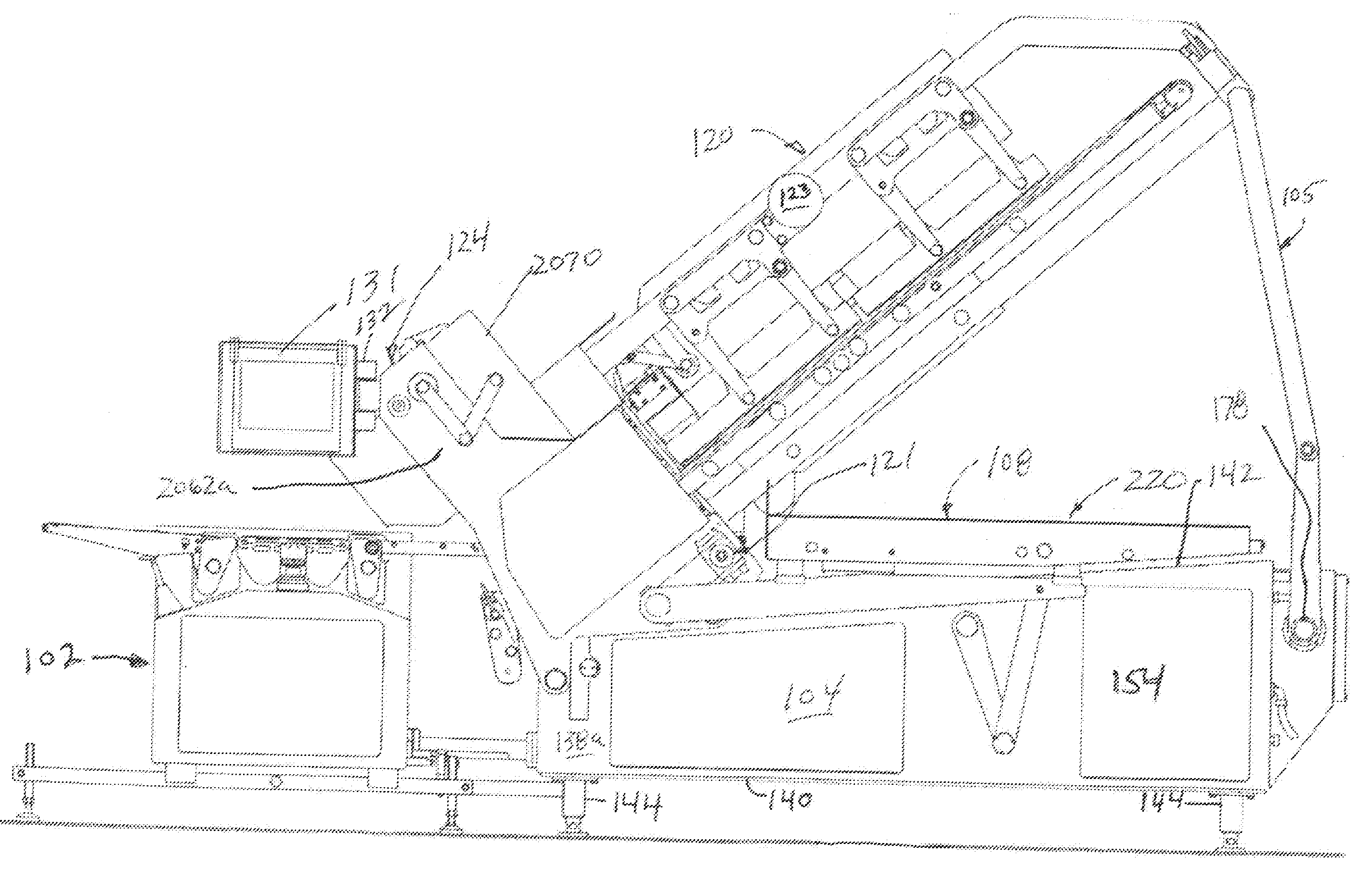
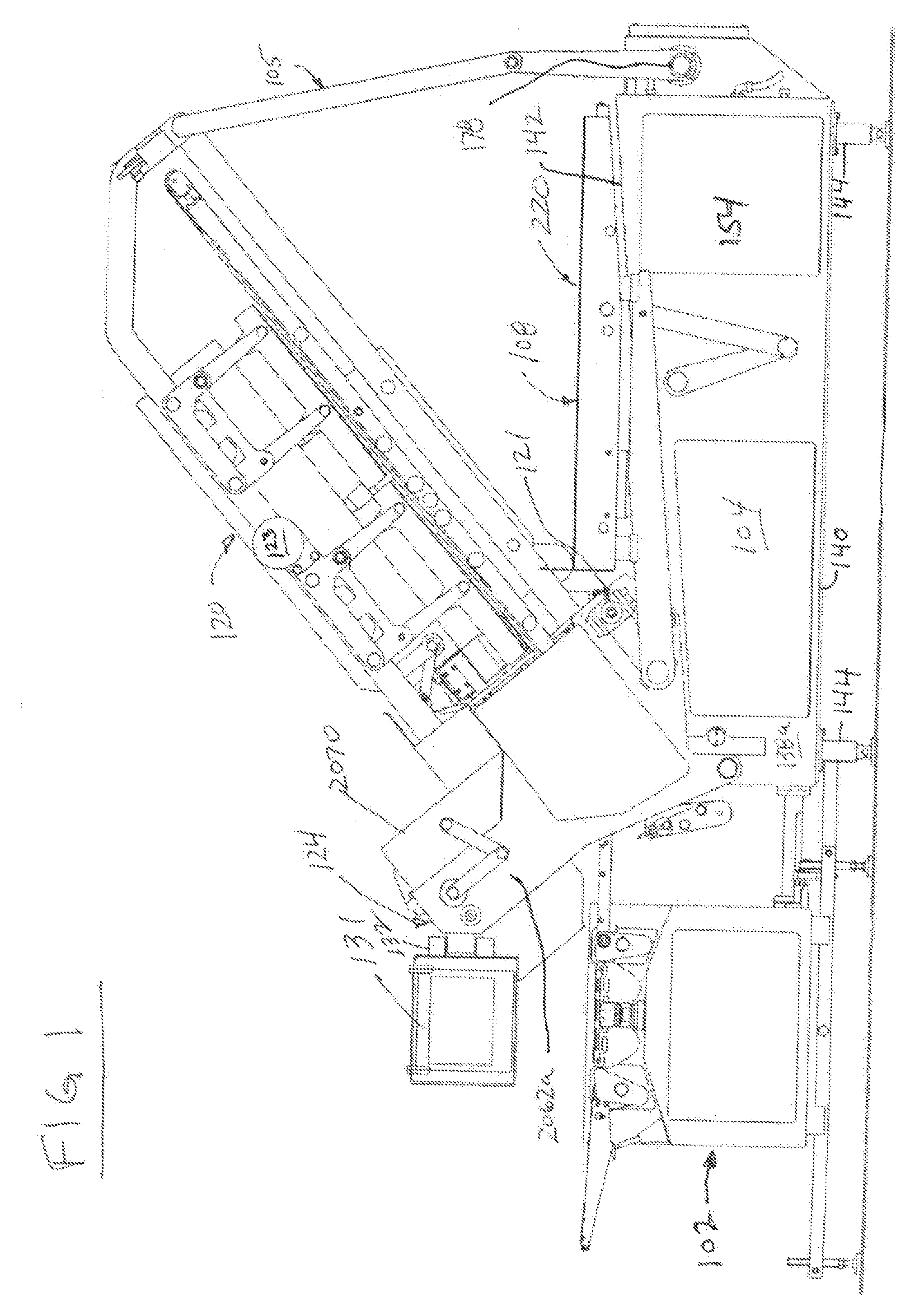
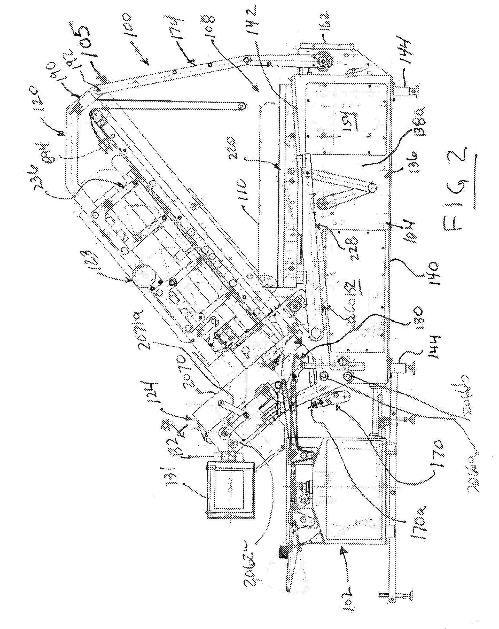
[0120]FIGS. 1-3 illustrate a high speed slicing apparatus 100 and a weighing and classifying conveyor or output conveyor 102 according to a preferred embodiment of the invention. The slicing apparatus 100 includes a base section 104, a collapsible frame 105, an automatic food article loading apparatus 108 that receives food articles 110 to-be-sliced, a food article feed apparatus 120, a food article feed elevation adjusting...


PUM

PropertyMeasurementUnit
Lengthaaaaaaaaaa
Diameteraaaaaaaaaa
Areaaaaaaaaaaa

Abstract

A food article feed apparatus for a food article slicing machine. The apparatus has conveyor with a drive belt for connecting a drive source to a drive roller, and a conveyor belt. The drive roller is for driving the conveyor. The drive roller has an outer diameter and a recessed diameter where the drive belt is connected around the recessed diameter and the conveyor belt is connected around the outer diameter. The drive belt operates within an area defined by the first conveyor belt.

Description

[0001]This application claims the benefit of U.S. Patent Application No. 60 / 999,961 filed on Oct. 22, 2007 and U.S. Patent Application No. 61 / 000,202 filed on Oct. 23, 2007.BACKGROUND OF THE INVENTION[0002]Many different kinds of food articles or food products, such as food slabs, food bellies, or food loaves are produced in a wide variety of shapes and sizes. There are meat loaves made from various meats, including ham, pork, beef, lamb, turkey, and fish. The meat in the food loaf may be in large pieces or may be thoroughly comminuted. These meat loaves come in different shapes (round, square, rectangular, oval, etc.) and in different lengths up to six feet (183 cm) or even longer. The cross-sectional sizes of the loaves are quite different; the maximum transverse dimension may be as small as 1.5 inches (4 cm) or as large as ten inches (25.4 cm). Loaves of cheese or other foods come in the same great ranges as to composition, shape, length, and transverse size.[0003]Typically the f...

Claims


Application Information

Patent Timeline
IPC IPC(8): B26D7/06
CPCB26D1/143Y10T409/30392B26D5/08B26D5/32B26D5/34B26D5/42B26D7/00B26D7/0608B26D7/0625B26D7/0683B26D7/088B26D7/22B26D7/30B26D7/32B26D2007/011B26D2210/02B26D2210/08B26D7/225B26D7/24F16P3/144Y10S83/932B26D7/06B26D5/00A22C17/0093B26D7/18Y10T83/7868Y10T83/061Y10T83/166Y10T83/081Y10T83/6945Y10T83/85Y10T83/6582Y10T83/95Y10T83/768Y10T83/6536Y10T83/6668Y10T83/662Y10T83/2048Y10T83/741Y10T83/6579Y10T83/2137Y10T83/04Y10T83/242Y10T83/6577Y10T83/647Y10T83/6616Y10T83/6563Y10T83/0467Y10T83/182Y10T83/531Y10T83/2192B26D1/36B26D1/02B26D1/157B26D1/165
Inventor PASEK, JAMES E.
Owner PROVISUR TECHNOLOGIES INC
Learn More