
Navigation Apparatus

a navigation apparatus and a technology of a navigation device, applied in the direction of mechanical control devices, instruments, manual control with a single controlling member, etc., can solve the problems of excessive length of time necessary inability to see the actual road map or consider, and inability to determine the final destination. , to achieve the effect of improving the convenience of operation

Inactive Publication Date: 2009-05-07
HONDA MOTOR CO LTD
View PDF2 Cites 1093 Cited by
  • Summary
  • Abstract
  • Description
  • Claims
  • Application Information

AI Technical Summary

Benefits of technology

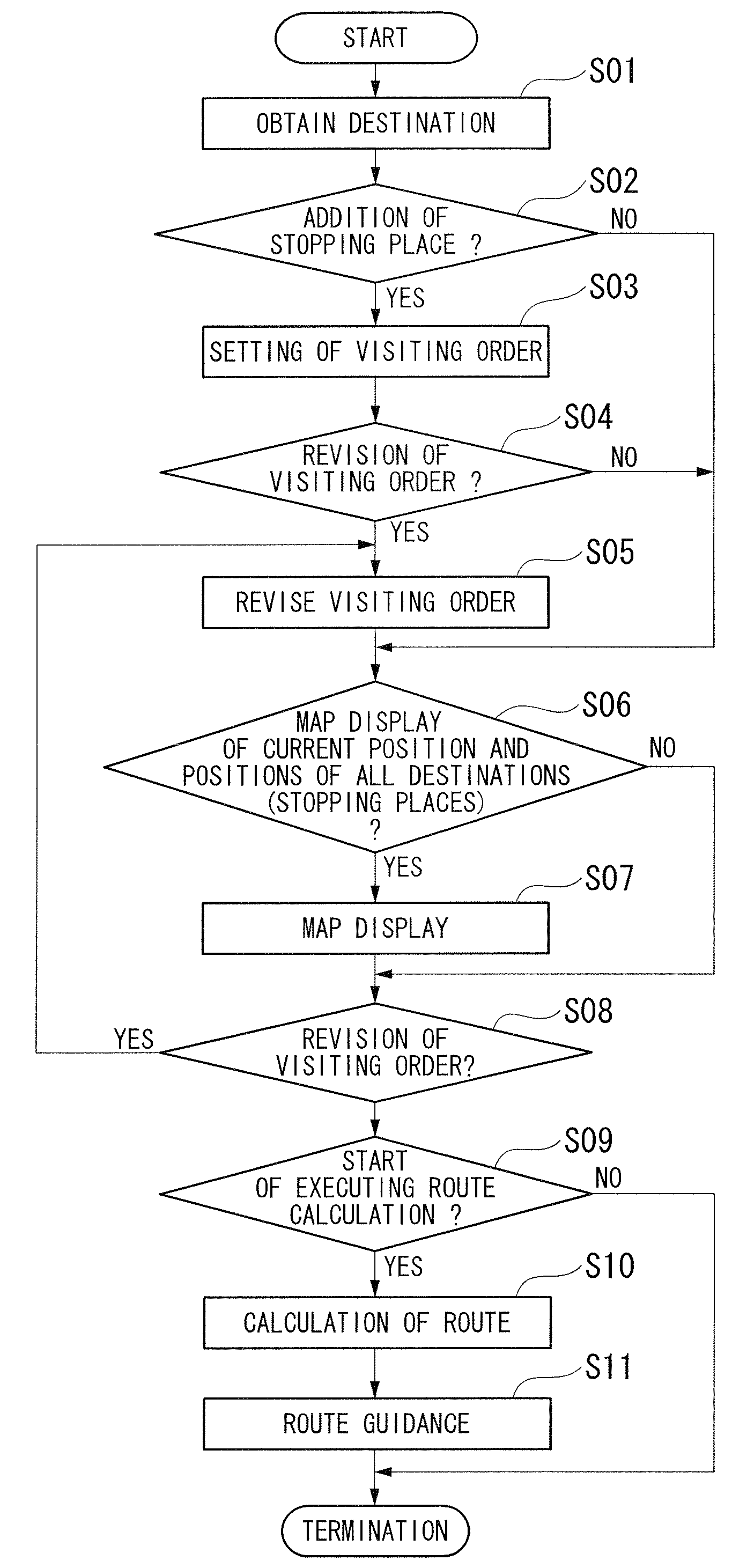
[0011]According to the navigation apparatus, when determining or revising visiting orders of a plurality of destinations, the current position and the positions of all the destinations are displayed on a map image. Therefore, an operator can see an actual road map and consider alternative selectable routes. Furthermore, the operation can be improved, even when operations such as addition / deletion of destinations and revision of visiting orders are repeatedly executed.
[0014]In this case, it is possible to prevent the calculation of unnecessary routes before the destinations and visiting orders are finalized. As a result, even where operations such as addition / deletion of destinations and revisions in visiting orders are repeatedly executed, it is possible to prevent excessive lengthening of the time necessary for finalizing the destinations and visiting orders.
[0019]According to the navigation apparatus, it is possible to further improve the convenience in the operation.

Problems solved by technology

Therefore, an operator of the navigation apparatus can not see the actual road maps or consider other routes that may be selected.
Thus, problems arise in that it is inconvenient, for example, in a case where the final destination or stopping places are repeatedly changed.
Thus, there is a concern that the time necessary to determine the final destination and the stopping places may be excessively lengthened.

Method used


Image

  • Navigation Apparatus
  • Navigation Apparatus
  • Navigation Apparatus

Examples


Embodiment Construction

[0034]Hereinafter, an explanation will be made for one embodiment of the navigation apparatus of the present invention by referring to the attached drawings.

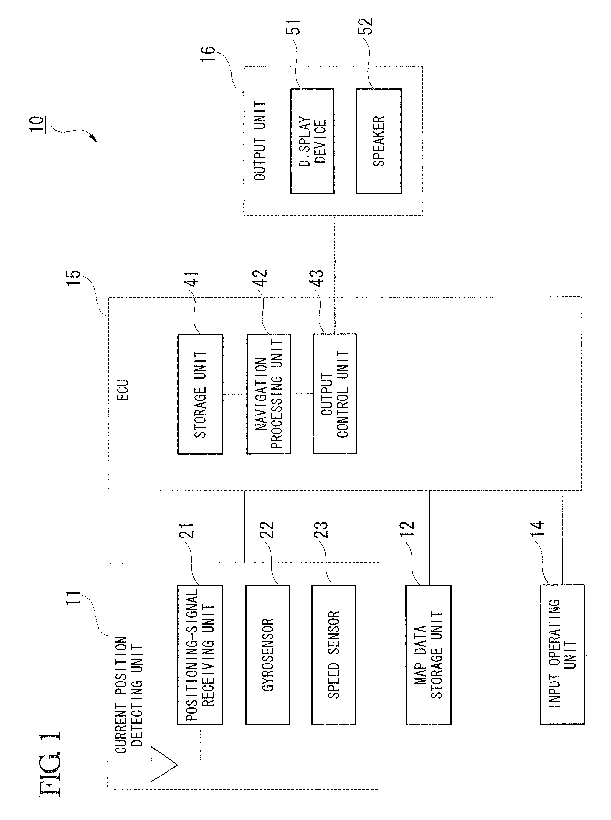
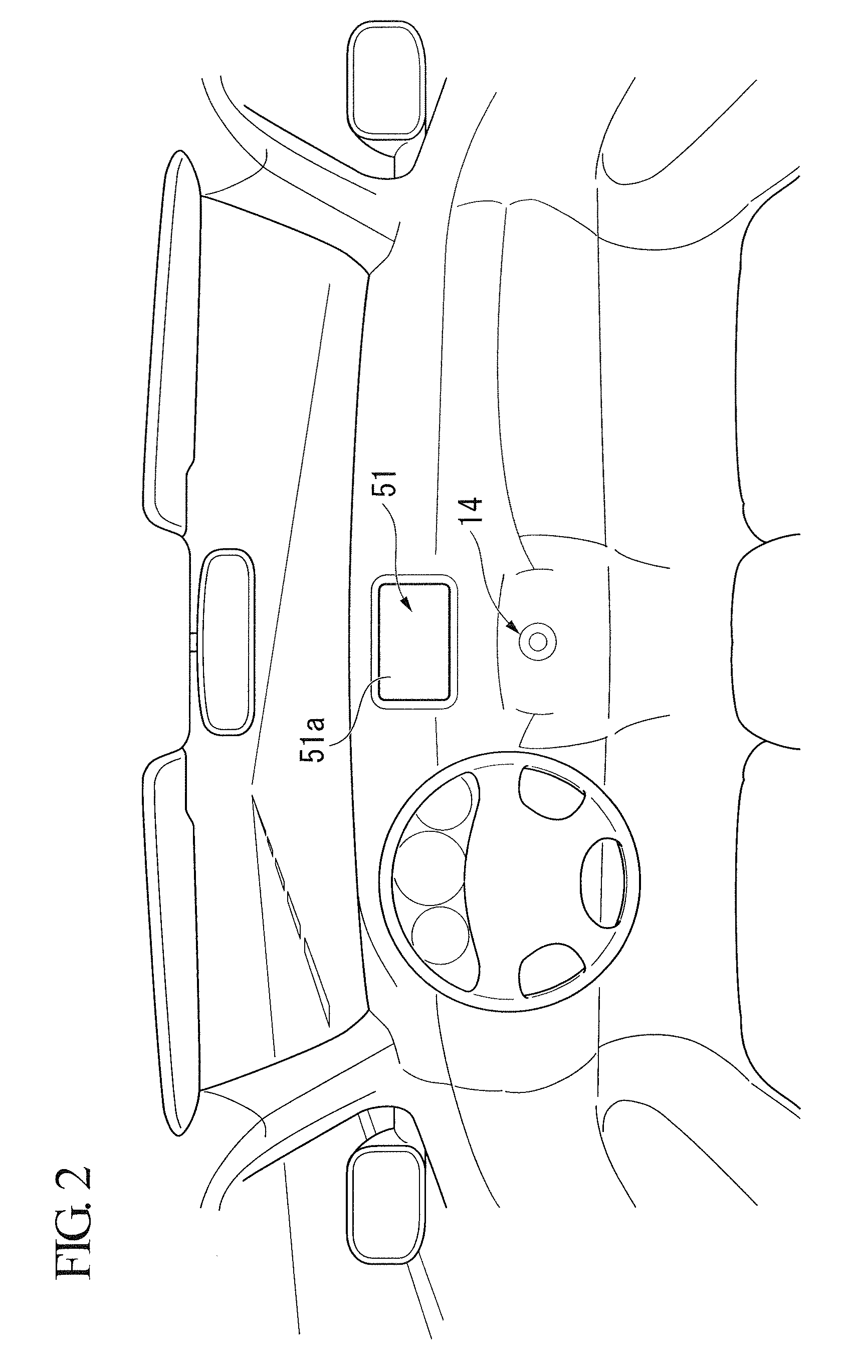
[0035]The navigation apparatus 10 of the present embodiment is, for example, as shown in FIG. 1, provided with a current position detecting unit 11, a map data storage unit 12, an input operating unit 14, an ECU 15 and an output unit 16.

[0036]The current position detecting unit 11 is provided with: a positioning-signal receiving unit 21 for receiving positioning signals, such as a GPS (Global Positioning System) signal for determining the position of a vehicle by utilizing an artificial satellite, and a DGPS (Differential Global Positioning System) signal for correcting errors in the GPS signal by utilizing any available base station to improve the positioning accuracy; a gyrosensor 22 for detecting the orientation of a vehicle within a horizontal plane, an inclined angle of a vehicle with respect to the perpendicular direction ...


PUM


Abstract

A navigation apparatus includes: an input operating unit; a map image storage member; a current position detecting member; a destination determination member; a visiting order determination member which determines a visiting order of each of the plurality of destinations in an revisable manner; a display control member which displays on the display member the map image on which the current position of the user and positions of all of the plurality of destinations are displayed; and a route calculation member which calculates a route from the current position by way of all of the plurality of destinations according to the visiting orders.

Description

BACKGROUND OF THE INVENTION[0001]1. Field of the Invention[0002]The present invention relates to a navigation apparatus.[0003]Priority is claimed on Japanese Patent Application No. 2007-289442, filed Nov. 7, 2007, the contents of which are incorporated herein by reference.[0004]2. Description of Related Art[0005]In the technical field of route guidance display from a departure place to a final destination by way of a plurality of destinations (stopping places), there is known a conventional navigation apparatus which summarize the relative positional relationships of individual stopping points in the whole route from the departure place to the final destination, and displays visiting orders of the individual stopping points (for example, refer to Japanese Unexamined Patent Application, First Publication No. H5-313572).[0006]A navigation apparatus related to the above-described conventional technology shows only summarized relative positional relationships of individual stopping poin...

Claims


Application Information

Patent Timeline
Patent Type & Authority Applications(United States)
IPC IPC(8): G01C21/26
CPCB60K37/06G05G2009/04781G05G2009/04777G01C21/36B60K35/10
Inventor KONDO, KEISUKEKINOSHITA, HIROFUMIMURAYAMA, TORU
Owner HONDA MOTOR CO LTD
Learn More