Emission device, surface light source device and display
- Summary
- Abstract
- Description
- Claims
- Application Information
AI Technical Summary
Benefits of technology
Problems solved by technology
Method used
Image
Examples
first modification
[0208](First Modification)
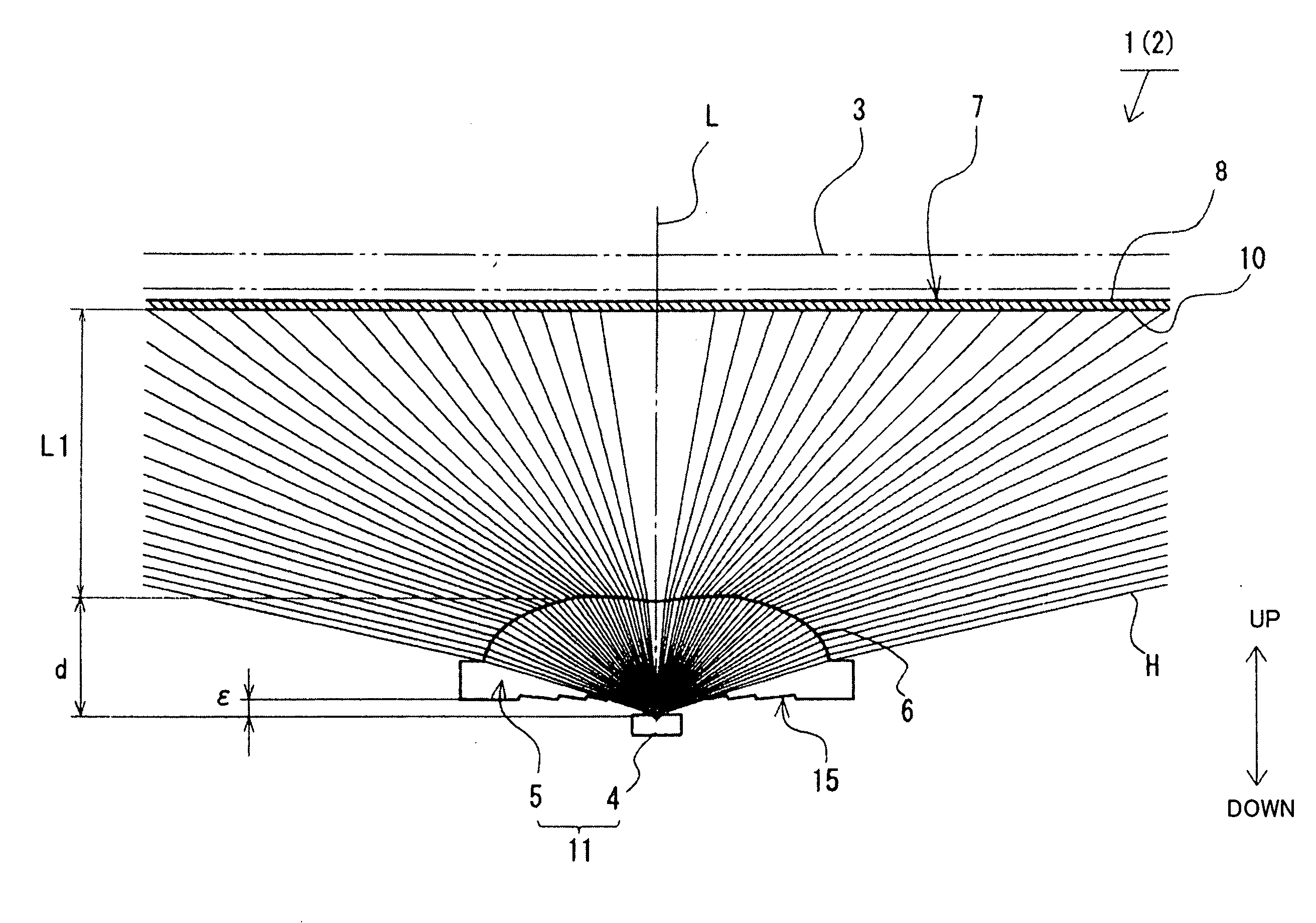
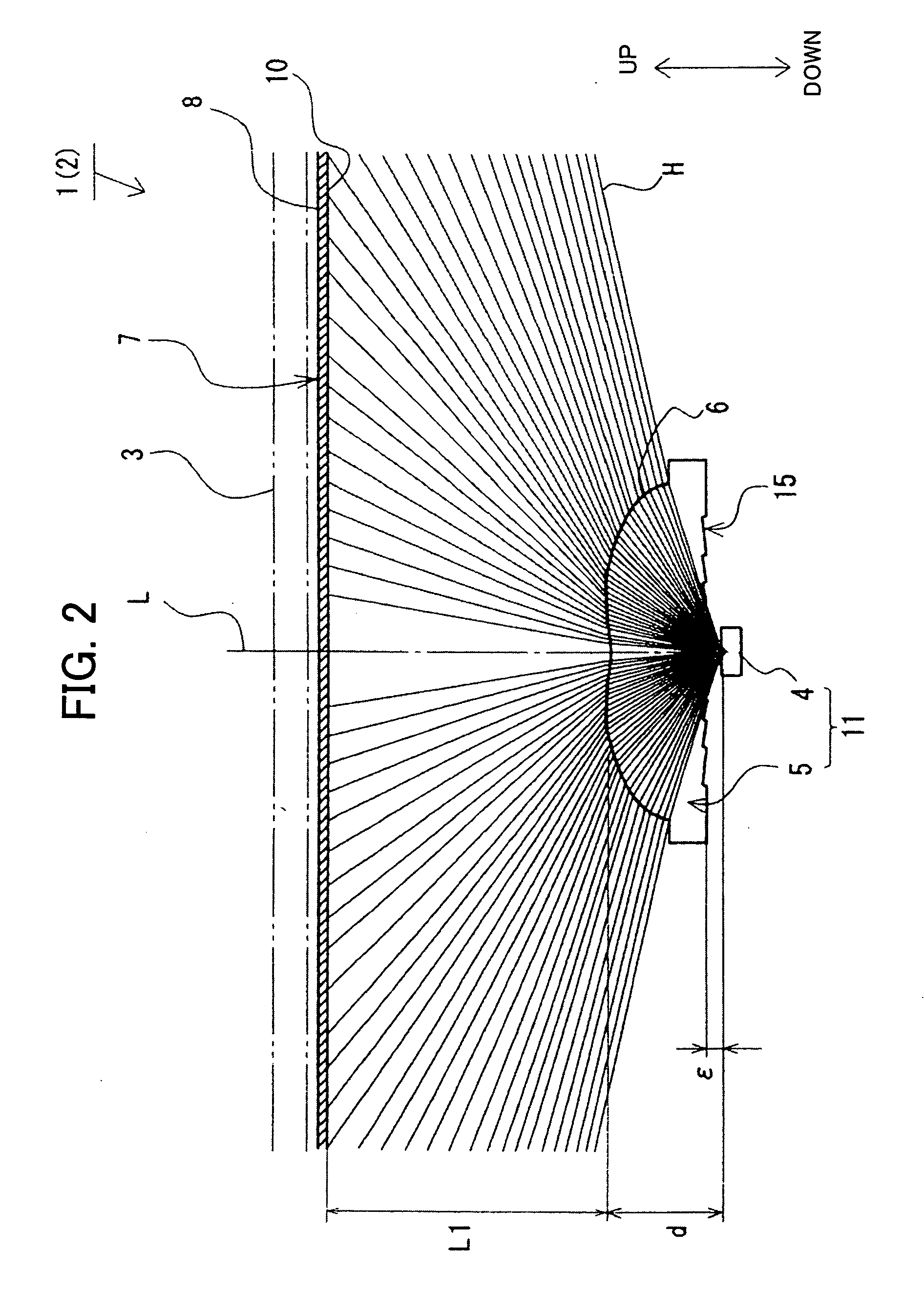
[0209]FIGS. 12a, 12b and 13 illustrate light flux control member 5 employed in a first modification of the present invention. It is noted that light flux control members 5 employed in the first modification and in second to third modifications described later are structured in the same way as light flux control member 5 employed in the embodiment already described except for recess portion(s) 15. Therefore common reference numerals are used for common elements and repeated description is omitted.
[0210]Referring to FIGS. 12a and 12b, light flux control member 5 has back face 12 provided with recess portions 15 consisting of first to eighth recess portions 15a to 15h. Respective recess portions 15a to 15h have the same cross section configuration. That is, first ring-like-recess-portion 15a has a triangle-like cross section, including first slope 15a1 generally located on an extended part of straight line 25 running from emitting point 13 to opening edge 24 o...
second modification
[0220](Second Modification)
[0221]FIGS. 14a, 14b and 15 illustrate light flux control member 5 employ ed in a second modification of the present invention.
[0222]Referring to FIGS. 14a and 14b, light flux control member 5 has back face 12 provided with a single ring-like recess portion 15. Ring-like recess portion 15 has a triangle-like cross section, provided with ring-like first slope 15a1 and ring-like second slope 15a2.
[0223]First slope 15a1 is generally located on an extended part of straight line 25 running from emitting point 13 to opening edge 24 of recess portion 14. Ring like second slope 15a2 providing a bridge portion connecting end portion 15a3 to a side of back face 12, being generally vertical to first slope 15a1.
[0224]Examples of factors are as follows.[0225]Radius r1 of recess portion 14; 1.5 mm[0226]Gap ε; 0.5 mm[0227]Angle α of line 25 with respect to reference plane C; 19.5°[0228]Angle θ of line 43 running through emitting point 13 and back face side end edge 42 of...
third modification
[0233](Third Modification)
[0234]FIG. 16 illustrates light flux control member 5 employed in a third modification.
[0235]Referring to FIG. 16, light flux control member 5 has back face 12 provided with a plurality of ring-like recess portions 15a to 15d which are arranged in order successively toward outside at a constant pitch L5 from recess portion 14.
[0236]Ring-like recess portion 15d has second slope 15d2, being formed so that back face side end edge 45 of second slope 15d2 is located at generally the same position as the position of back face side end edge 33 of second slope 15d2 of forth ring-like recess portion 15d in the embodiment described above. In the third modification, the outermost ring-like recess portion is ring-like recess portion 15d.
[0237]Examples of factors are as follows.[0238]Radius r1 of recess portion 14; 1.5 mm[0239]Gap ε; 0.5 mm[0240]Angle α of line 25 with respect to reference plane C; 19.5°[0241]Angle θ of line 46 running through emitting point 13 and bac...
PUM
 Abstract
Description
Claims
Application Information
 - R&D
- Intellectual Property
- Life Sciences
- Materials
- Tech Scout
- Unparalleled Data Quality
- Higher Quality Content
- 60% Fewer Hallucinations
Browse by: Latest US Patents, China's latest patents, Technical Efficacy Thesaurus, Application Domain, Technology Topic, Popular Technical Reports.
© 2025 PatSnap. All rights reserved.Legal|Privacy policy|Modern Slavery Act Transparency Statement|Sitemap|About US| Contact US: help@patsnap.com


