Method for Vehicle Creep Torque Control

a technology of creep torque and control method, which is applied in the direction of mechanical equipment, instruments, transportation and packaging, etc., can solve the problems of increasing the energy consumption of the motor, reducing the efficiency of creep torque application, and reducing the efficiency of creep torque, so as to reduce the energy consumption and reduce the energy consumption of creep torque. , the effect of reducing the energy consumption of creep torqu

Active Publication Date: 2009-05-07
GM GLOBAL TECH OPERATIONS LLC
View PDF8 Cites 11 Cited by
  • Summary
  • Abstract
  • Description
  • Claims
  • Application Information

AI Technical Summary

Benefits of technology

[0007]An advantage of an embodiment is reduced energy usage since the energy needed for creep torque is minimized while the vehicle is stationary, but the desired creep torque feel is still provided to the driver when needed during vehicle start-up. Moreover, the creep torque feel may even be improved somewhat since, while stopped in a creep torque situation, the brakes are not unnecessarily working against a creep torque produced by the vehicle.

Problems solved by technology

For some newer types of vehicles where an engine is not operating all of the time, applying creep torque is more of a challenge.
However, the extra energy used by the motor to maintain the creep torque while the vehicle is stopped while in gear somewhat defeats the purpose of implementing these non-conventional powertrains in the new types of vehicles.

Method used


Image

  • Method for Vehicle Creep Torque Control
  • Method for Vehicle Creep Torque Control
  • Method for Vehicle Creep Torque Control

Examples


Embodiment Construction

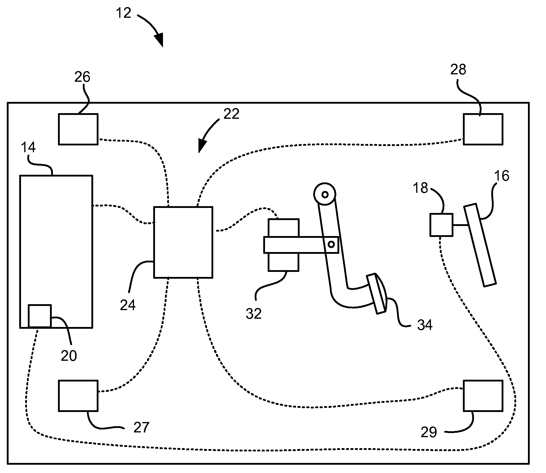
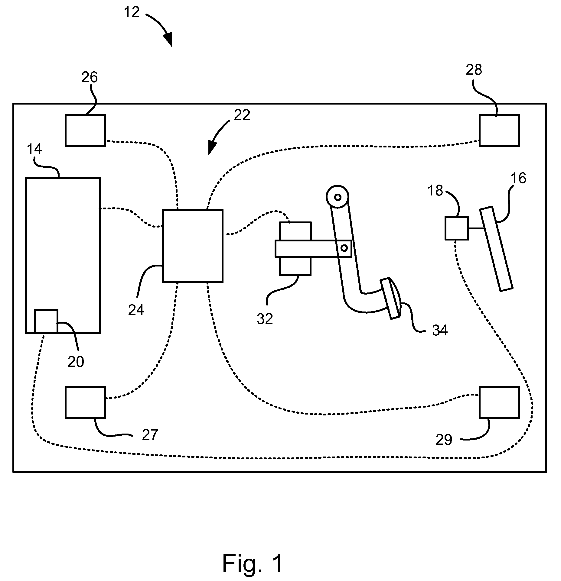
[0010]Referring to FIG. 1, a vehicle, indicated generally at 12, is shown. The vehicle 12 includes a powertrain system 14 having variable creep torque capability, such as, for example, two-mode hybrid, battery electric, and fuel cell vehicles. A driver operated accelerator pedal 16 may include a position sensor 18 that communicates the pedal position to a powertrain controller 20.

[0011]The vehicle also includes a brake system 22 having a brake controller 24 that controls the braking pressure applied by a right-front wheel brake 26, a left-front wheel brake 27, a right-rear wheel brake 28 and a left-rear wheel brake 29. A brake position sensor 32 detects the position of a driver operated brake pedal 34 and communicates the position to the brake controller 24. The brake controller 24 may be separate from or a portion of another controller and may be any desired combination of hardware or software as is known to those skilled in the art. The brake pressure may be applied to the brakes ...


PUM


Abstract

A vehicle and a method of operation is disclosed. The method of operating the vehicle may include a method of controlling a creep torque in a vehicle having a powertrain configured to provide variable creep torque. The method may comprise the steps of: detecting a vehicle creep torque condition, determining a brake torque, and adjusting a creep torque applied by the powertrain based on the brake torque.

Description

BACKGROUND OF INVENTION[0001]The present invention relates generally to a method for controlling creep torque in a vehicle.[0002]Automotive vehicles typically have a vehicle technical specification that defines how fast the particular vehicle should accelerate from a stop when it is idling in gear and the driver applies no pressure to the brake pedal or the accelerator pedal. To accomplish this, the powertrain system is designed to apply a specific amount of torque when the vehicle is stopped, called creep torque. This creep torque, then, acts against the brake application by the driver while the vehicle is stopped. Upon release of the brake pedal, the vehicle will begin to move, even without pressing on the accelerator pedal. In a vehicle with a conventional internal combustion engine, automatic transmission and torque converter, applying a creep torque is relatively easy since the engine is operating all of the time—even while the vehicle is stopped at a traffic light.[0003]For so...

Claims


Application Information

Patent Timeline
Patent Type & Authority Applications(United States)
IPC IPC(8): B60K17/00G06F7/00B60W30/18
CPCB60W10/04B60W10/184Y10T477/646B60W2520/30B60W2540/12B60W30/18063
Inventor SCHWARZ, JONATHAN R.KIDSTON, KEVIN S.LOGAN, JON K.
Owner GM GLOBAL TECH OPERATIONS LLC
Why Eureka
Try Eureka