
Blade Insert Illuminator

a technology of illuminating devices and blade inserts, applied in the field of medicine, can solve the problems of poor deep tissue illumination, limited illumination in these procedures, and poor illumination of the deep tissue, and achieve the effects of efficient light transmission system, and minimal light loss from waveguides

Active Publication Date: 2009-04-30
INVUITY
View PDF99 Cites 74 Cited by
  • Summary
  • Abstract
  • Description
  • Claims
  • Application Information

AI Technical Summary

Benefits of technology

[0013]A blade insert illuminator must be designed and fabricated to maximize light transfer from the light source or fiber optic input cable and minimize light loss from the waveguide in order to provide an efficient light transmission system. Efficiency is particularly important for LED and other light sources, e.g., halogen or xenon lamps, because it directly determines the required brightness of the LED. An inefficient waveguide experiences significant light loss, typically 60% of light may be lost from input to output. Such a light guide would require a high power LED to provide sufficient light. A high power LED requires a lot of power and generates significant heat, thereby requiring large batteries and bulky and inconvenient heat sinking devices and methods that add to the size and increase the difficulty of using such a device. Other high power light sources often require noisy fans, which may disturb the medical personnel conducting a surgery or medical exam. Lamps used in high power light sources have a limited life time, requiring frequent and expensive replacement, due to the need to drive the lamp at high power levels to generate enough light. An efficient waveguide, one in which light loss is typically less than 30%, allows a much lower power LED or other light source to be used, thereby significantly reducing or eliminating the need for special heat sinking devices and methods, reducing cost, and improving the usability of the device. The design of an efficient blade insert illumination waveguide may involve special design of the light input portion of the waveguide to efficiently capture the incoming light, for example, by careful selection of numerical apertures or using a lens, design and fabrication of the light reflecting walls of the light conducting portion of the waveguide to maintain surface finish to maximize reflection and reduce light lost through refraction, the use of reflective or dampening coatings, the design of light directing optical structures that direct the light toward the light output optical structures while minimizing light loss through refraction, and or the design of light output optical structures that maximize light exiting the waveguide through refraction, particularly refraction of light in certain directions, while minimizing light lost through reflection.
[0014]A blade insert illumination system includes one or more illumination elements composed of a transparent or semi-transparent polymer that is preferably biocompatible and sterilizable. The illumination elements operate as a waveguide and may incorporate optical components such as, for example, symmetric or asymmetric facets, lenses, gratings, prisms and or diffusers to operate as precision optics for customized delivery of the light energy. The illumination elements may be modular, allowing components to be mixed and matched for different sizes of blade retractors, or may be a single integrated unit. Each module may also have different performance characteristics such as a diffuse light output or a focused light output allowing users to mix and match optical performance as well.

Problems solved by technology

Illumination in these procedures is typically limited to external illumination sources such as ceiling or wall mounted lights or light sources integrated into a headband worn by the surgeon (e.g., LED based or fiber optic based).
These light sources provide poor illumination of the deep tissue on which surgery is to be performed.
Fiber optic devices may be fixed to a blade retractor to shine light on the deep tissue, but fiber optic systems either provide a small spot of light requiring constant repositioning to view all the tissue, or they provide a very diffuse light that does not adequately illuminate the tissue of interest.
Any debris or blood that covers it will block the majority of illumination.
Furthermore, fiber optic devices are very expensive, requiring specialized cutting, grinding and polishing.
Blade insert illumination devices are currently limited to fiber optic approaches with their poor illumination characteristics.
An inefficient waveguide experiences significant light loss, typically 60% of light may be lost from input to output.
A high power LED requires a lot of power and generates significant heat, thereby requiring large batteries and bulky and inconvenient heat sinking devices and methods that add to the size and increase the difficulty of using such a device.
Other high power light sources often require noisy fans, which may disturb the medical personnel conducting a surgery or medical exam.
Lamps used in high power light sources have a limited life time, requiring frequent and expensive replacement, due to the need to drive the lamp at high power levels to generate enough light.

Method used


Image

  • Blade Insert Illuminator
  • Blade Insert Illuminator
  • Blade Insert Illuminator

Examples


Embodiment Construction

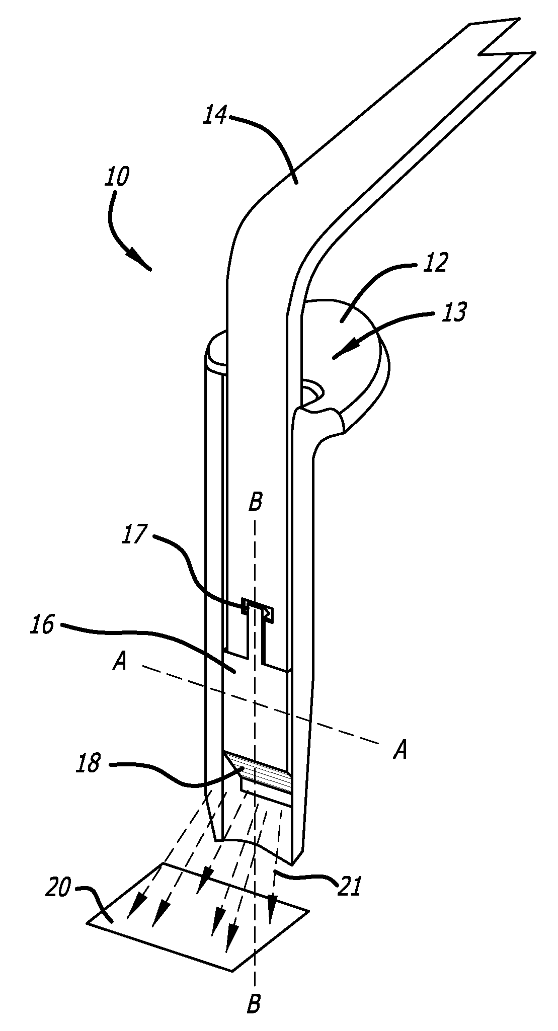
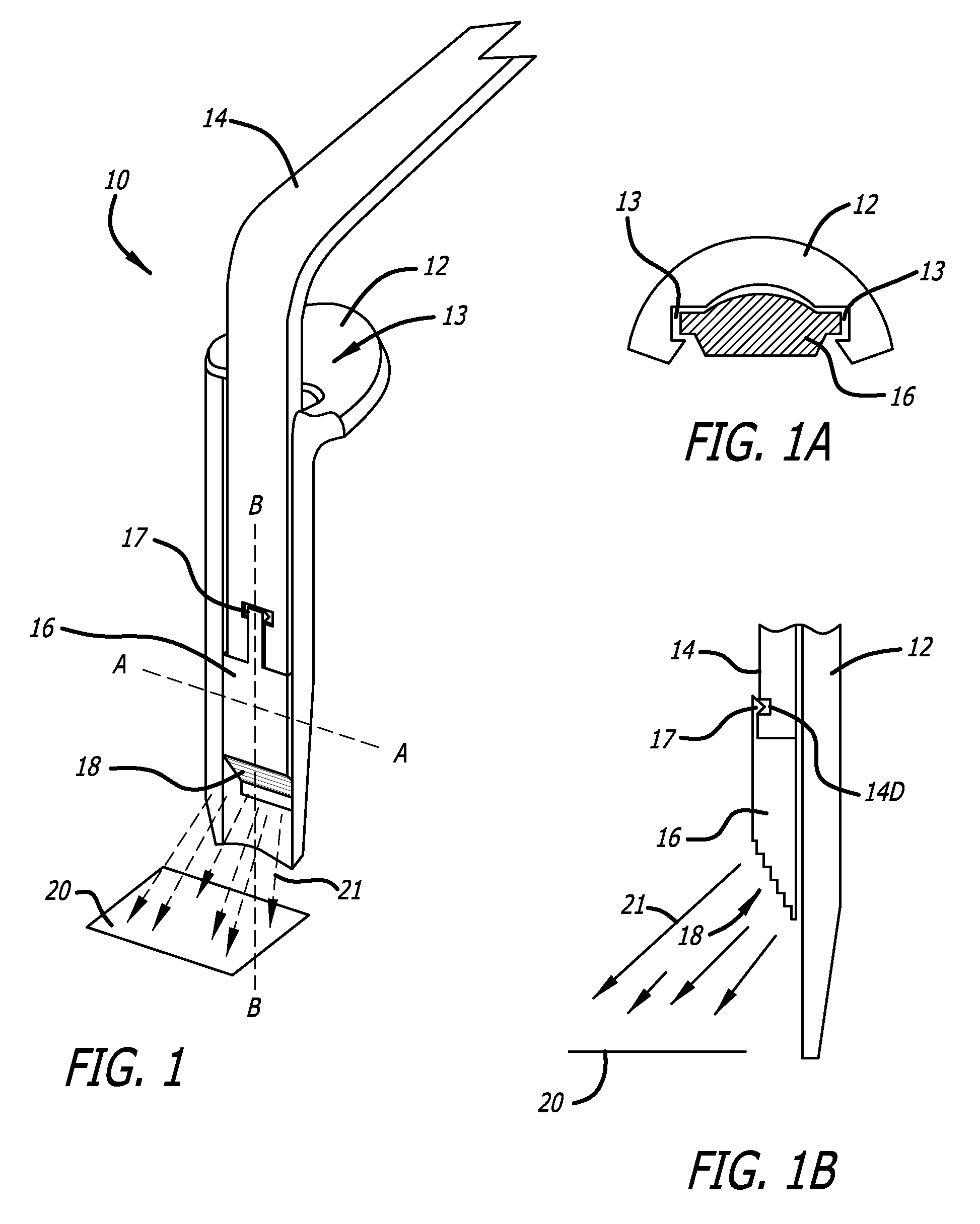
[0038]Retractor illumination system 10 of FIG. 1 includes blade retractor 12 including channel 13 to engage a fiber optic input 14 and waveguide illuminator 16. Latch 17 serves to mechanically attach waveguide illuminator 16 to fiber optic input 14 so that the resulting assembly may be moved up and down in channel 13 to any position suitable for illumination. The optical coupling between fiber input 14 and waveguide illuminator 16 is a simple face-to-face coupling, which may be enhanced by use of an index matching gel, or other similar material, applied to either the fiber input 14 or the waveguide illuminator 16 or both. Light entering waveguide illuminator 16 is contained within the waveguide with minimal light loss until it reaches output optical structures such as output structures 18, where light exits to illuminate the predetermined illumination area 20. Output optical structures 18 may include one or more stair stepped facets or lenses that may include a radius or angled face...


PUM


Abstract

An air gap retractor illumination system includes any suitable retractor such as a McCulloch with a channel in the blade to accommodate an air gap illuminator. The illuminator is preferably made from a suitable light conducting plastic material such as acrylic or polycarbonate or silicone. The illuminator has active portions in which light passes and inactive or dead zones in which light does not pass as a result of the configuration and orientation of the input, output and surfaces of the illuminator. The illuminator is formed to have an air gap surrounding any active portion of the illuminator extending from the light input to the light output portion. The dead zones may include elements to allow the illuminator to securely engage the retractor. The light output portion of the illuminator contains from two to eight output zones, each zone having specially designed output optical structures that control and direct light to escape the illuminator to shine onto a predetermined area of interest or to form one or more predetermined shapes or footprints.

Description

FIELD OF THE INVENTIONS[0001]The inventions described below relate to the field of medicine and more specifically, to providing in vivo surgical field illumination during surgical procedures.BACKGROUND OF THE INVENTIONS[0002]Surgical procedures often employ the use of retractors to separate and hold tissue to expose the underlying tissue on which the procedure is to be performed. Blade retractors are a type of retractor that typically have a flat or slightly curved blade that is inserted into the body. The blade may have a handle portion that is used to manipulate the blade. One or more blade retractors may be used in a surgical procedure. Illumination in these procedures is typically limited to external illumination sources such as ceiling or wall mounted lights or light sources integrated into a headband worn by the surgeon (e.g., LED based or fiber optic based). These light sources provide poor illumination of the deep tissue on which surgery is to be performed. Fiber optic devic...

Claims


Application Information

Patent Timeline
IPC IPC(8): A61B1/32
CPCA61B17/02A61B19/36A61B19/5202A61B1/0623A61B2019/521A61B1/07A61B17/0218A61B2019/5206A61B90/80A61B90/30A61B2090/309A61B2090/306
Inventor GREY, THOMAS L.VAYSER, ALEXGASSON, JONATHAN G.TRAUNER, KENNETH B.
Owner INVUITY
Learn More