
Illumination device having one or more lumiphors, and methods of fabricating same

a technology of lumiphor and illumination device, which is applied in the field of light emitters, can solve the problems of less efficient conversion of red phosphor, less efficient conversion of warm white light emitters which include light emitting diodes,

Inactive Publication Date: 2009-04-30
CREE INC
View PDF101 Cites 237 Cited by
  • Summary
  • Abstract
  • Description
  • Claims
  • Application Information

AI Technical Summary

Benefits of technology

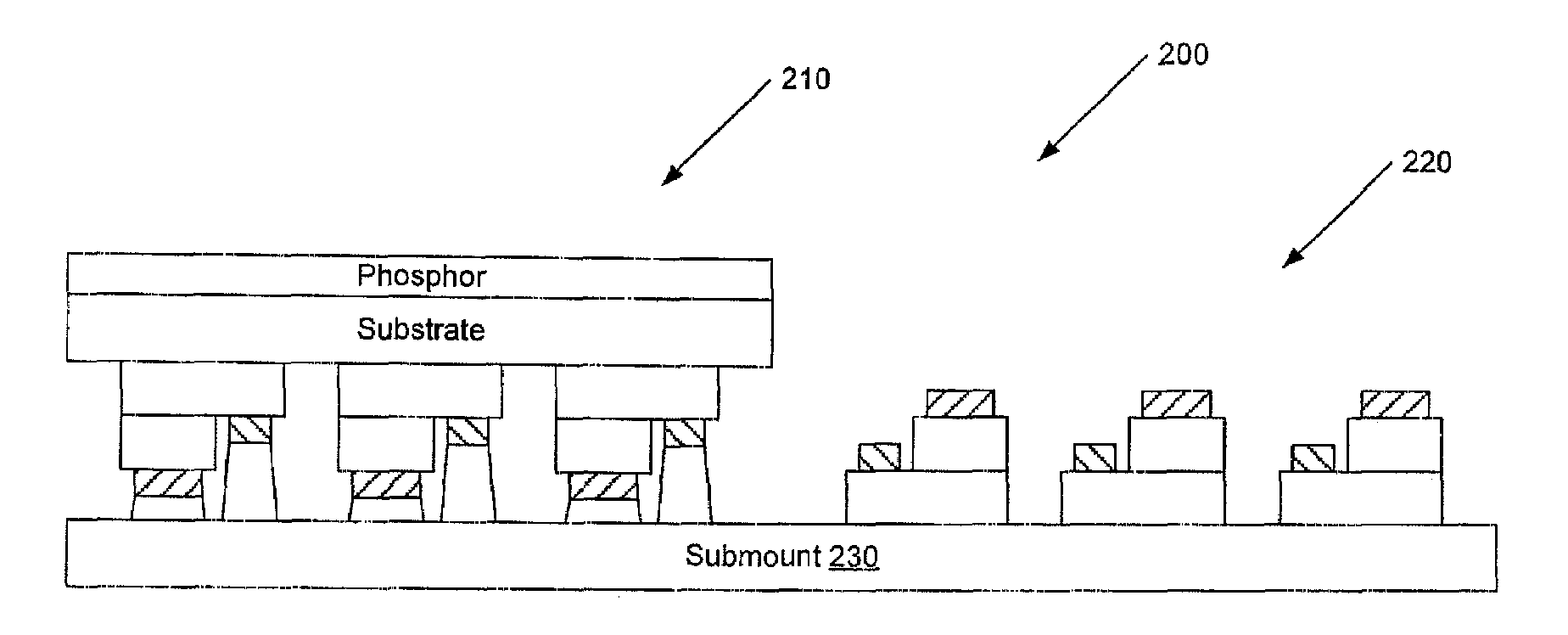
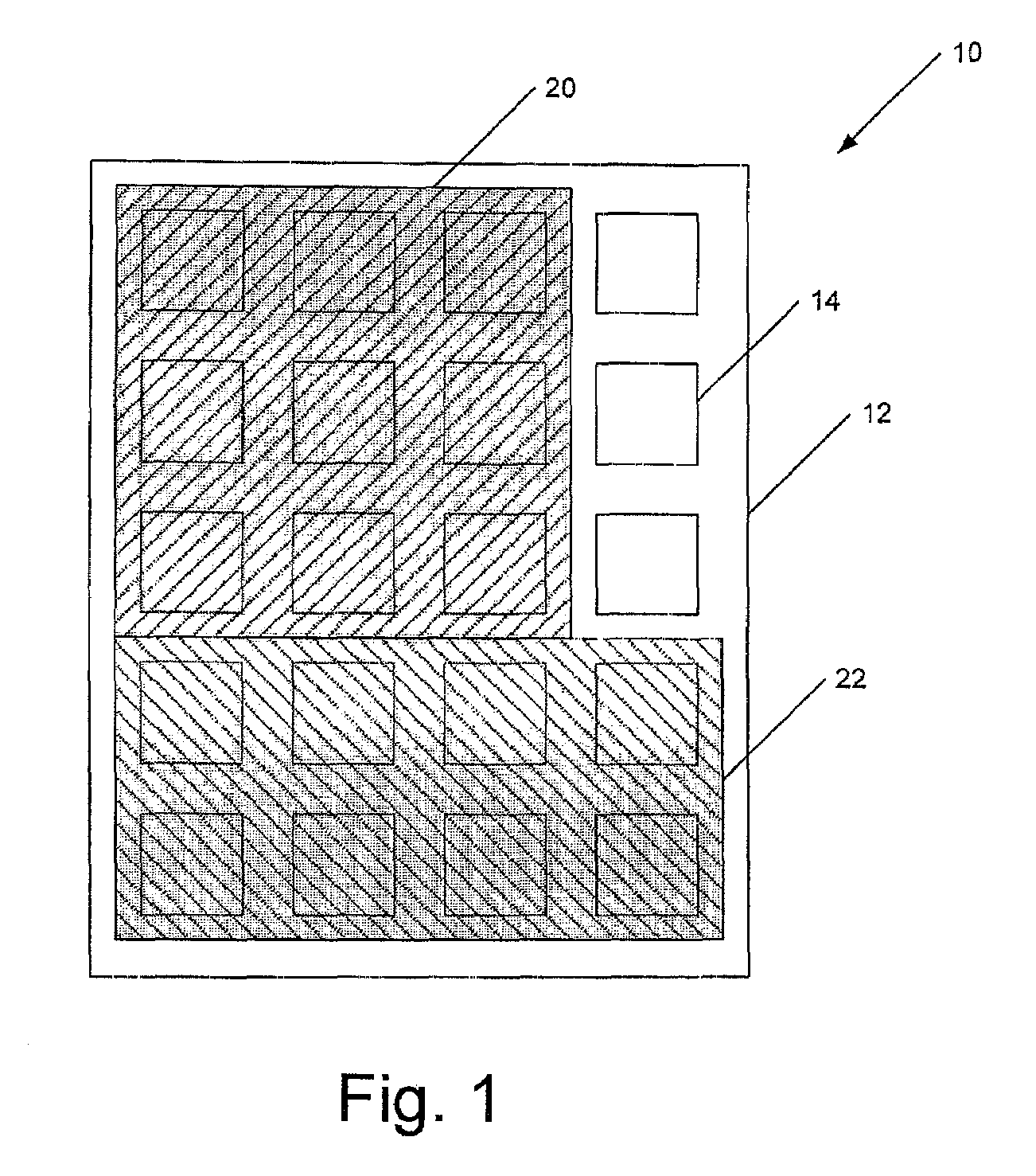
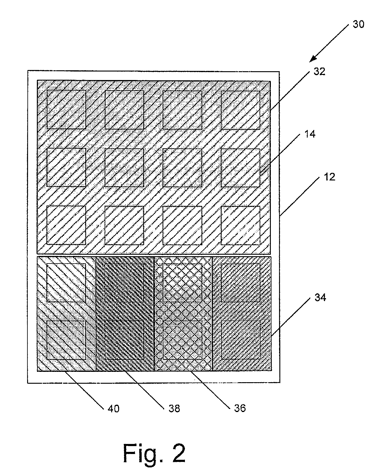
[0020]at least a first lumiphor (or a pattern of first lumiphors) on the die, the first lumiphor (or pattern of first lumiphors) covering less than all of a light emission region of the monolithic die such that a first portion of light emitted by the at least one solid state light emitting device is directed into the first lumiphor (or pattern of first lumiphors) and a second portion of light emitted by the at least one solid state light emitting device is not directed into the first lumiphor (or pattern of ...

Problems solved by technology

In contrast, a red phosphor will typically be less efficient in the conversion.
Thus, warm white light emitters which include light emitting diode devices tend to be less efficient than cooler color temperature white light emitters which include light emitting diode devices.

Method used


Image

  • Illumination device having one or more lumiphors, and methods of fabricating same
  • Illumination device having one or more lumiphors, and methods of fabricating same
  • Illumination device having one or more lumiphors, and methods of fabricating same

Examples


Embodiment Construction

[0095]The present inventive subject matter now will be described more fully hereinafter with reference to the accompanying drawings, in which embodiments of the inventive subject matter are shown. However, this inventive subject matter should not be construed as limited to the embodiments set forth herein. Rather, these embodiments are provided so that this disclosure will be thorough and complete, and will fully convey the scope of the inventive subject matter to those skilled in the art. Like numbers refer to like elements throughout. As used herein the term “and / or” includes any and all combinations of one or more of the associated listed items.

[0096]The terminology used herein is for the purpose of describing particular embodiments only and is not intended to be limiting of the inventive subject matter. As used herein, the singular forms “a”, “an” and “the” are intended to include the plural forms as well, unless the context clearly indicates otherwise. It will be further unders...


PUM


Abstract

A light emitter comprising a monolithic die comprising at least one solid state light emitting device and at least a first lumiphor covering part of a light emission region of the die. In some embodiments, at least a second lumiphor is provided on the die. The first lumiphor can be part of a first pattern of lumiphors, and / or the second lumiphor can be part of a second pattern of lumiphors. The first and second lumiphors can differ in luminescent material, size, shape and / or concentration of luminescent material. The lumiphors can overlap completely, partially, or not at all. Some embodiments comprise an electrical interconnection to electrically connect respective solid state light emitting devices. Also, a light emitter comprising unit cells each comprising a group of light emitting devices and at least one lumiphor. Methods of fabricating light emitters comprise selectively applying at least one lumiphor to a monolithic die.

Description

CROSS-REFERENCE TO RELATED APPLICATIONS[0001]This application claims the benefit of U.S. Provisional Patent Application No. 60 / 982,900, filed Oct. 26, 2007, the entirety of which is incorporated herein by reference.FIELD OF THE INVENTION(S)[0002]The present inventive subject matter relates to light emitters and, more particularly, to light emitters suitable for use in lighting applications.BACKGROUND OF THE INVENTION(S)[0003]Light emitting diode devices that utilize a phosphor to convert light from one wavelength to another are well known. For example, blue light emitting diode devices with a yellow phosphor, such as YAG:Ce, are utilized to create white light. Such light, however, typically has a relatively low color rendering index (CRI) and a relatively high correlated color temperature (CCT). As the CCT of the light is reduced to produce “warm white” light, e.g. a CCT of 3500K, the efficiency of the light emitting diode device / phosphor system is typically reduced. This is the cas...

Claims


Application Information

Patent Timeline
IPC IPC(8): H01L33/00
CPCH01L27/156H01L33/504H01L33/508H01L2924/12041H01L2924/13091H01L24/14H01L2924/00
Inventor NEGLEY, GERALD H.VAN DE VEN, ANTONY PAUL
Owner CREE INC
Learn More