Tire sealant dispensing apparatus

Inactive Publication Date: 2009-04-30
TRANS TECH PRODS
View PDF23 Cites 54 Cited by
  • Summary
  • Abstract
  • Description
  • Claims
  • Application Information

AI Technical Summary

Benefits of technology

[0007]It is a purpose of the present invention to provide a tire repair and inflation apparatus which may be used to inject a tire sealant of a chosen viscosity into a tire both to repair tire punctures after they occur, as well as to provide preventative to the loss of air on future puncture occurrence without removal of a tire valve core. In accordance with the foregoing, the present invention comprises a pressurizable container in which a sealant liquid composition is located. The container is provided with an outlet line to connect the container to the valve stem of a tire to be treated, and an inlet port connectable to a source of compressed gas, such as an air compressor. In a preferred embodiment the container includes a valve system such that the compressed gas entering the container pressurizes the container to drive the sealant liquid into the tire while at the same time feeding amounts of the pressurizing gas into the tire, assisting in the delivery and dispersion of the liquid within the tire. Backflow prevention from the tire into the container is also provided. The apparatus may preferably be used without removal of the tire valve stem core as it allows a variety of sealants, having a wide range of viscosities, to pass through the valve and not block the valve stem core, and thus can be used without full deflation of the tire. Both sealant and air can be delivered simultaneously; the tire need not be reconnected to a separate inflation device.

Problems solved by technology

Such a methodology has the deficiencies that the tire must be removed from the vehicle and the location of the puncture found.
Rotation of the tire causes the sealant to spread over the inner surface of the tread area, sealing the leak.
The quantity of sealant in the can is often limited, and there is a limited amount of compressed gas in the container to drive the fluid.
Often such containers do not have sufficient contents to re-inflate a punctured tire sufficiently to allow the tire to be driven on safely; the partially-inflated tire exposes the tire rim to increased damage from potholes or other road hazards.
They also do not prevent future puncture leaks.
These systems require the valve core of the tire to be removed and the tire deflated, as the viscous sealant used would clog the valve core, and any pressure in the tire would prevent the user from squeezing the bottle to force the sealant into the tire.

Method used


Image

  • Tire sealant dispensing apparatus
  • Tire sealant dispensing apparatus
  • Tire sealant dispensing apparatus

Examples


Embodiment Construction

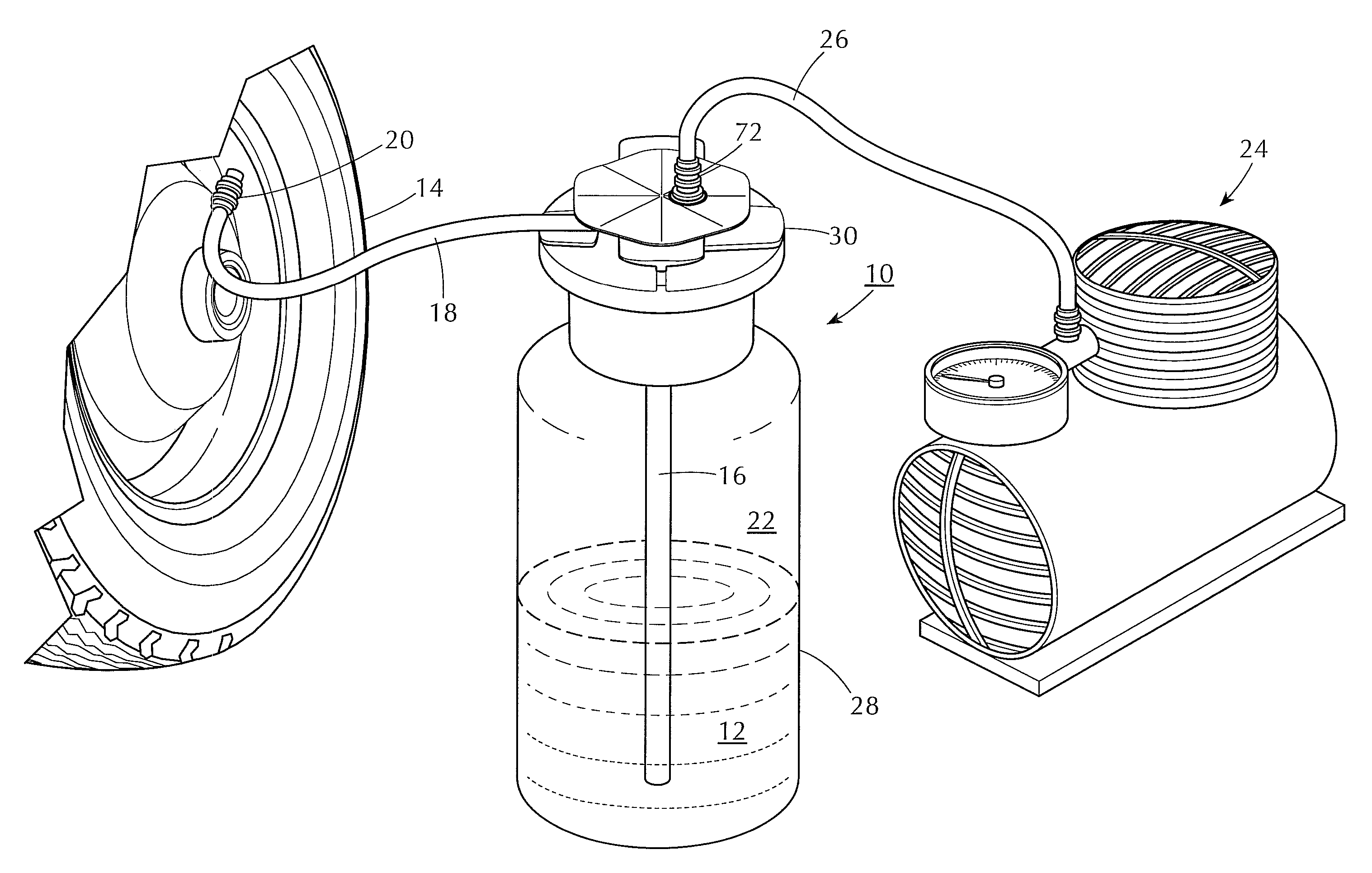
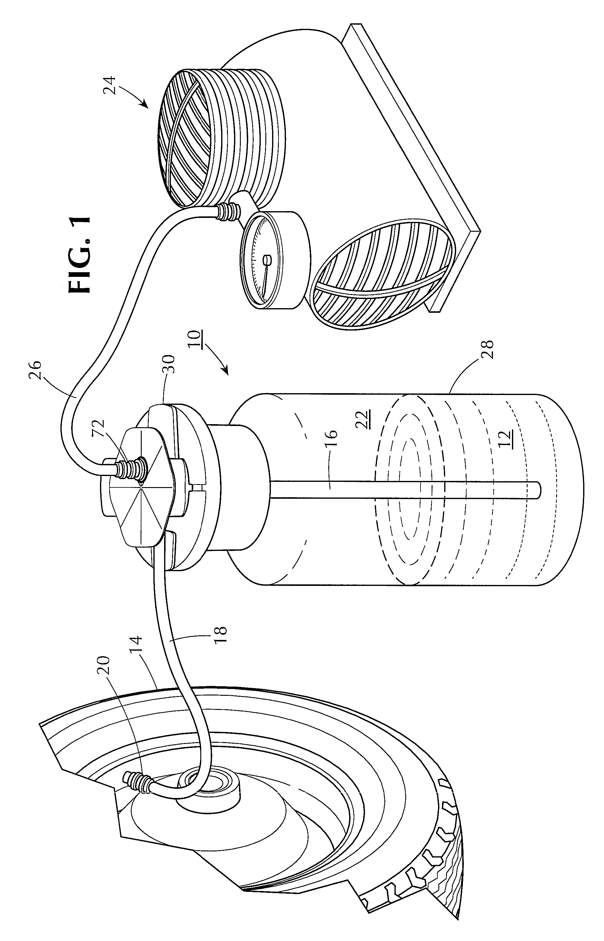
[0014]With initial reference to FIG. 1, the present invention comprises a container assembly 10 for a quantity of sealant fluid 12 intended to be injected into tire 14 to either seal a pre-existing puncture hole or to serve as a prophylactic against loss of air from the tire through a subsequent puncture. The sealant may be of a type generally known in the trade, including vinyl or cellulose-based types, with binders and clotting agents of the general type known in the art. The fluid contents 12 of the container assembly are directed upward through dip tube 16 and delivered to the interior of the tire through outlet tube 18, which terminates in a connector 20 of known construction that attaches to the inflation valve stem of the tire. The air space 22 above the sealant fluid 12 in the container assembly is pressurized to drive the fluid through the dip tube and outlet tube into the tire. The internal container pressure is developed by a suitable source of compressed gas, such as air...


PUM

PropertyMeasurementUnit
Forceaaaaaaaaaa
Pressureaaaaaaaaaa
Flow rateaaaaaaaaaa

Abstract

A tire-sealing apparatus for injecting a sealing composition into a vehicle tire either as a prophylactic or for sealing an existing leak is in the form of a pressurizeable container for a flowable sealant compound. An inlet is provided for introducing compressed gas into the container to pressurize its contents. An outlet line is also provided to deliver the sealant into a tire, the pressurized gas acting on contents of the container and providing the motive force for the delivery. A dip tube extends into the compound and is coupled to a one-way valve to provide a controlled flow of the compound from the container into the tire while preventing back pressure of the tire from either delivering air or compound back into the container. A passageway between the outlet tube and an interior of the container is provided to allow a flow of compressed gas within the container into the outlet tube along with the sealant.

Description

[0001]The present invention relates to an apparatus and method for dispensing a measured amount of a fluid under pressure and in particular to an apparatus for dispensing tire sealant into a vehicle tire. Applicants claim the benefit of U.S. Provisional Application 60 / 983,423 filed Oct. 29, 2007, the contents of which are incorporated by reference herein.BACKGROUND OF THE INVENTION[0002]Vehicle tire repair technology is well developed. In one well known aspect, a tire, such as an automobile or truck tire, damaged and deflated by a puncture, such as by a nail, is demounted from the vehicle and the puncture point located. An elastomeric plug is inserted into the puncture hole creating an airtight seal. The tire can then be re-inflated and re-installed on the vehicle. Such a methodology has the deficiencies that the tire must be removed from the vehicle and the location of the puncture found. When the puncture-causing object no longer is in the tire some degree of skill and care is req...

Claims


Application Information

Patent Timeline
IPC IPC(8): B65B3/10B65B3/00B65D49/02B65B31/02
CPCB05B9/0805B65D83/756B29L2030/00B29C73/166
Inventor TRACHTENBERG, SAULCOWAN, DAVIDMCLAUGHLIN, NEAL
Owner TRANS TECH PRODS
Why Eureka
Try Eureka