
Communication System Using Passive Optical Network and Passive Optical Network

a communication system and optical network technology, applied in the field of communication systems, can solve the problems of complex management, inability to execute snmp, tftp, tftp communication, etc., and achieve the effect of convenient installation

Inactive Publication Date: 2009-04-23
HITACHI LTD
View PDF26 Cites 21 Cited by
  • Summary
  • Abstract
  • Description
  • Claims
  • Application Information

AI Technical Summary

Benefits of technology

[0019]It is an object of the invention to provide a PON system which can be easily installed by a communication carrier in which a CMTS and a CM have already been installed in place of the CMTS and the CM without largely changing peripheral apparatuses or system such as an apparatus management system and the like and without largely changing a communication system of a PON interval from a PON standard and which can make management similar to that of the CMTS and the CM.
[0028]According to the invention, the communication carrier in which the CMTS and the CM have already been installed can easily install the PON merely by installing the optical fiber and providing the PON system of the invention with hardly modifying the apparatus management system. Moreover, since the same apparatus management system as that for the CMTS and the CM can be used, the system administrator can easily manage the PON and can also suppress an additional investment to the apparatus management system. Owing to the installation of the PON, the access line of a speed of 1 Gbits / sec or higher which cannot be provided by the cable Internet using the coaxial cable can be provided to the subscriber.

Problems solved by technology

The cable Internet in which the coaxial cable is used for the access line is disadvantageous in terms of a line speed as compared with the PON in which the whole interval of the access line is the optical fiber.
However, a part of the data structure is unique to the DOCSIS standard and other communicating apparatuses including the OLT and the ONU do not cope with such a part of the data structure.
Therefore, the ONU itself does not execute communication of the SNMP, TFTP, and Time protocols as communication using an IP layer.
In such a case, however, since it is necessary that both of an apparatus management system for the CMTS / CM and an apparatus management system for the PON are provided for an upstream apparatus management network, the management becomes complicated.
Further, although a method of integrating only a user interface for management of both of them is also considered, large development costs are required in such a case.

Method used


Image

  • Communication System Using Passive Optical Network and Passive Optical Network
  • Communication System Using Passive Optical Network and Passive Optical Network
  • Communication System Using Passive Optical Network and Passive Optical Network

Examples


Embodiment Construction

[0046]A construction and the operation of a communication system using a PON of the invention will be described in detail hereinbelow with reference to the drawings. Although an example in which a GE-PON which has been standardized by the IEEE standard 802.3ah is used as a PON of the invention will be described hereinbelow, the invention can be also embodied by applying another PON such as a GPON or the like which has been standardized by the ITU-T standard G.983.

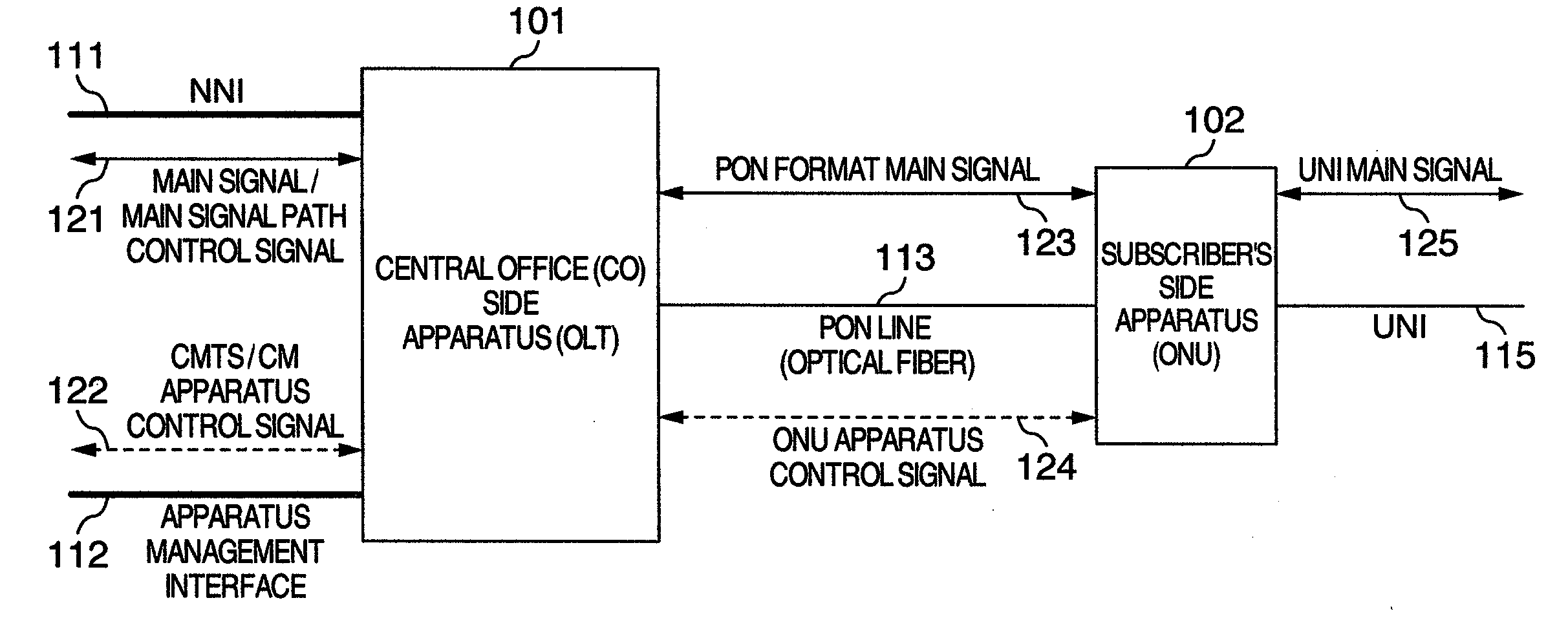
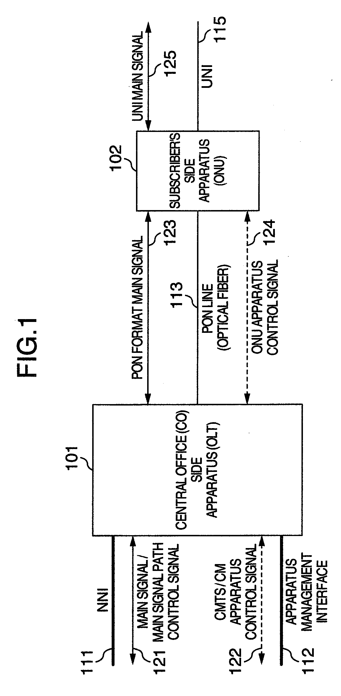
[0047]FIG. 1 is an explanatory diagram showing an example of a construction of apparatuses of the PON and a communication interface and a construction of signals which are transmitted and received.

[0048]The PON of the invention is constructed by an OLT 101 as a station side apparatus and an ONU 102 as a subscriber's side apparatus. In an interval between the OLT 101 and the ONU 102 (PON interval), they are connected by a PON line 113. Generally, a physical media of the PON line 113 is an optical fiber. Although a constructi...


PUM


Abstract

An OLT transmits and receives a CMTS / CM apparatus control signal through an apparatus physical management interface which is physically identical to or different from a main signal interface (NNI) and processes the CMTS apparatus control signal by itself. When connection of a new ONU is detected by an ONU apparatus control signal, an IP address is allocated by using the CM apparatus control signal in a manner similar to the CM. The CM apparatus control signal regarding the ONU is transmitted and received by using the IP address and a mutual conversion is performed between the CM apparatus control signal and the ONU apparatus control signal. The ONU processes the ONU apparatus control signal in a manner similar to the ONU based on an ordinary PON standard.

Description

INCORPORATION BY REFERENCE[0001]The present application claims priority from Japanese application JP2007-269647 filed on Oct. 17, 2007, the content of which is hereby incorporated by reference into this application.BACKGROUND OF THE INVENTION[0002]1. Field of the Invention[0003]The invention relates to a communication system which is constructed by an optical fiber line, an optical splitter, and apparatuses arranged at both ends thereof, which enables transmission and reception of a data packet between the apparatuses at both ends, and which enables one of the apparatuses to make management and setting of the other apparatus, wherein a passive optical network (hereinbelow, abbreviated to PON) is used as a network constructed by presuming use of a CMTS (Cable Modem Termination System) and a CM (Cable Modem).[0004]2. Description of the Related Art[0005]In recent years, video distribution services of an IP (Internet Protocol) base mainly according to a video-on-demand form by a communi...

Claims


Application Information

Patent Timeline
IPC IPC(8): H04J14/00H04L12/44
CPCH04L12/2861H04L41/0213H04Q2011/0088H04Q11/0067H04Q2011/0079H04L41/0226
Inventor TSUGE, MUNETOSHIMORI, TAKASHIKOBAYASHI, MASANOBUMIYAMORI, YOSHIOGOHARA, SHINOBU
Owner HITACHI LTD
Learn More