
Low Power Fast Impulse Radio Synchronization

Active Publication Date: 2009-04-23
ZEBRA TECH CORP
View PDF9 Cites 11 Cited by
  • Summary
  • Abstract
  • Description
  • Claims
  • Application Information

AI Technical Summary

Benefits of technology

[0015]The term “powering down” includes disabling at least a portion of a component in such a way that overall power requirement is reduced.
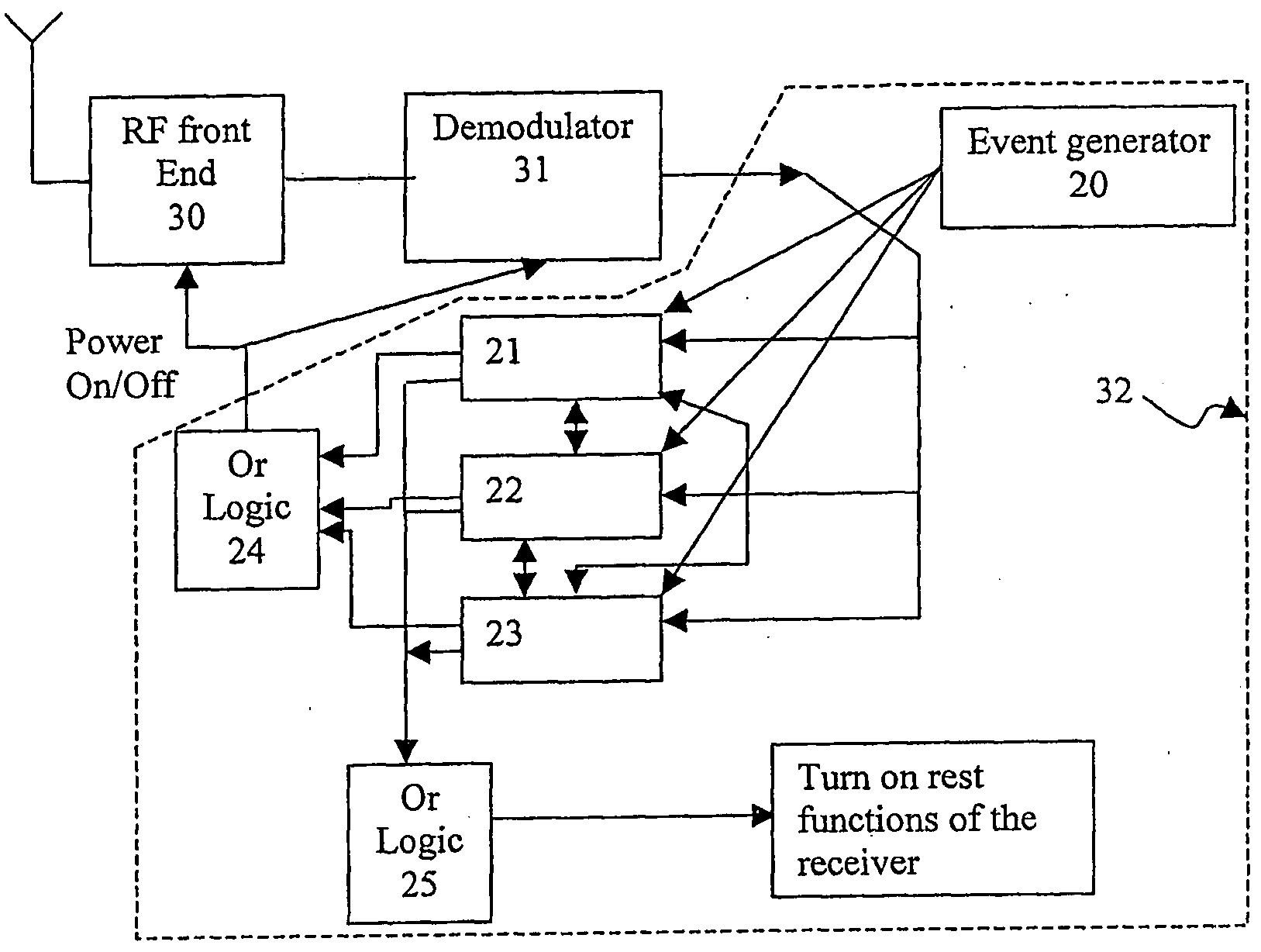
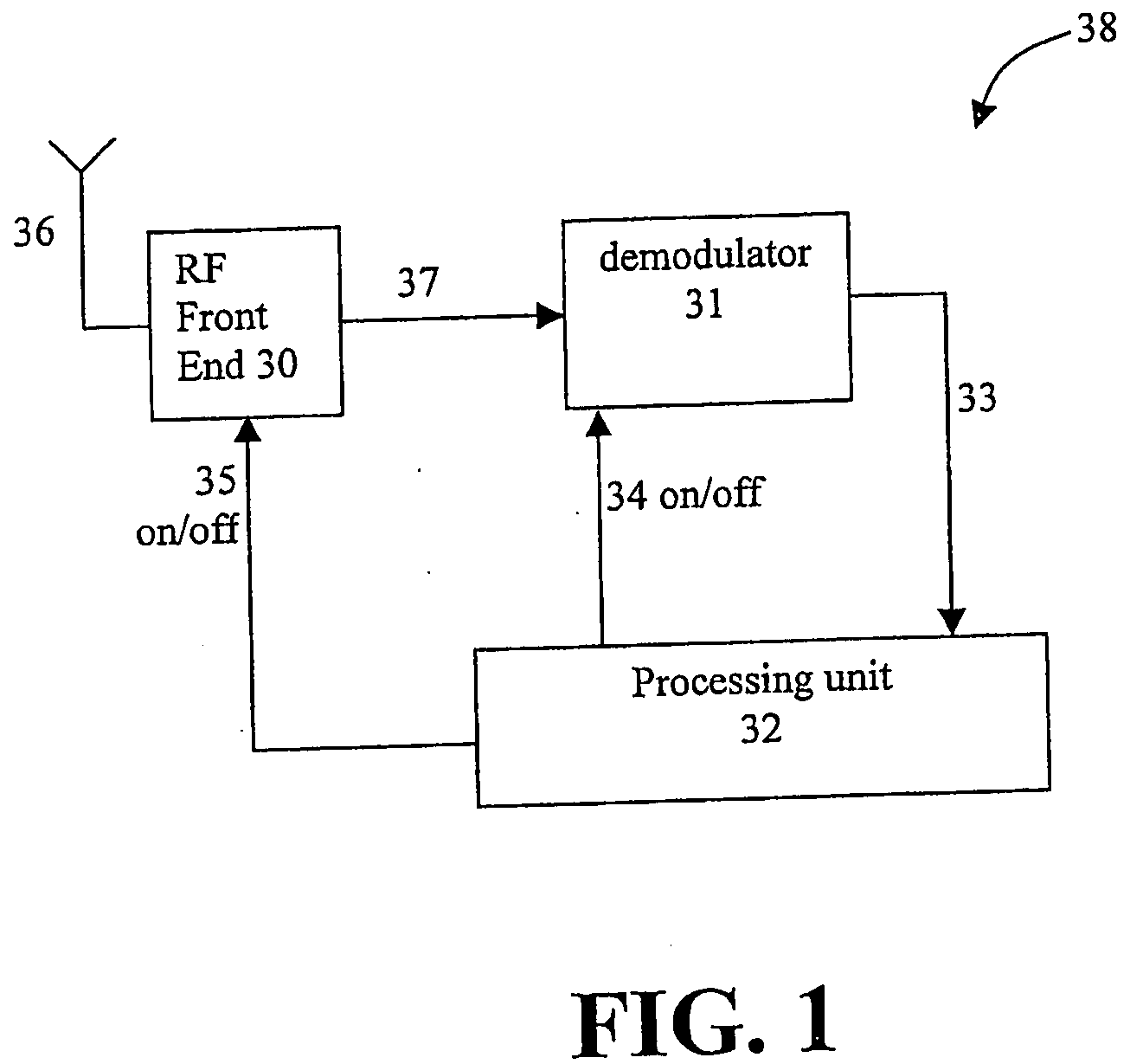
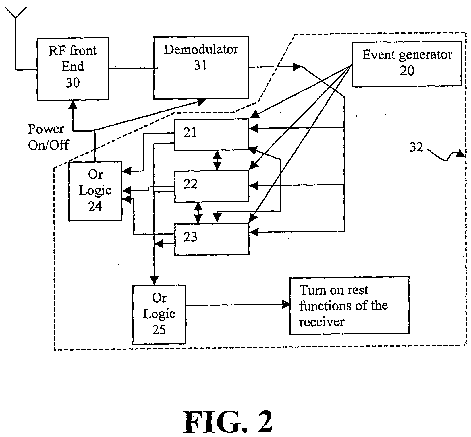
[0018]According to the present invention there is provided a method for synchronizing on a pulsed waveform sequence including pulsed waveforms. An impulse radio receiver is provided including a radio frequency (RF) front end connected to a demodulator, and the demodulator is connected to a processing unit. Power is provided to at least a portion of an RF component such as the RF front end and / or the demodulator, during time windows sufficient for testing an hypothesis regarding timing of the pulsed waveforms. The powering is controlled by the processing unit. Preferably, testing the hypothesis includes accumulating a signal of the pulsed waveforms, correlating with the pulsed waveforms, or accumulating the correlation result of the pulsed waveforms. Preferably, others functions of the receiver are powered or enabled subsequent to the testing. Preferably, the impulse radio receiver is an ultra-wide band receiver. Preferably, the pulsed waveform includes a series of pulses modulated by a binary sequence. Preferably, multiple hypotheses are tested and the powering allows testing the multiple hypotheses in parallel regarding timing of the pulsed waveform sequence. Preferably, the pulsed waveform sequence is scanned for and acquired by the processing unit even when the acquisition of the pulsed waveform sequence is achieved with a non-negligible probability of a false alarm; and performance is maintained despite the non-negligible probability of a false alarm. Preferably, the time interval between consecutive pulsed waveforms is uniform. Preferably, the scanning is performed every T1 seconds, wherein T1 is not an integral multiple of a time interval between consecutive pulsed waveforms. Preferably, the method further storing state variables pertaining to the receiver; powering down the component of the receiver; and powering up and restoring the component of the receiver. Upon reading the state variables, powering up and restoring is expedited. Preferably, restoring includes restoring an oscillator frequency.

Problems solved by technology

Apart from the fact that two circuits are needed, there is no outline of how to save power while acquiring the pulsed waveform.

Method used


Image

  • Low Power Fast Impulse Radio Synchronization
  • Low Power Fast Impulse Radio Synchronization
  • Low Power Fast Impulse Radio Synchronization

Examples


Embodiment Construction

[0024]The present invention relates to fast impulse radio synchronization used for acquiring quickly an impulse radio synchronization sequence and achieving a low average power consumption. The present invention is primarily directed to applications of communication systems based on a non-continuous transmission wherein the interval between transmissions is predictable. Moreover, the present invention enables the reception of more than one packet concurrently.

[0025]The principles and operation of a system and method according to the present invention, may be better understood with reference to the drawings and the accompanying description.

[0026]Before explaining embodiments of the invention in detail, it is to be understood that the invention is not limited in its application to the details of design and the arrangement of the components set forth in the following description or illustrated in the drawings. The invention is capable of other embodiments or of being practiced or carri...


PUM


Abstract

A method for synchronizing on a pulsed waveform sequence including pulsed waveforms. An impulse radio receiver is provided including a radio frequency (RF) front end connected to a demodulator, and the demodulator is connected to a processing unit. Power is provided to at least a portion of an RF component such as the RF front end and / or the demodulator, during time windows sufficient for testing an hypothesis regarding timing of the pulsed waveforms. The powering is controlled by the processing unit. Preferably, testing the hypothesis includes accumulating a signal of the pulsed waveforms, correlating with the pulsed waveforms, or accumulating the correlation result of the pulsed waveforms. Preferably, others functions of the receiver are powered or enabled subsequent to the testing. Preferably, the impulse radio receiver is an ultra-wide band receiver.

Description

CROSS REFERENCE TO RELATED APPLICATIONS[0001]The present application is a national phase application under 35 U.S.C. 371 of international application PCT / IL2005 / 00506 filed 15 May 2005 which claims the benefit from U.S. provisional application 60 / 570,468 filed 13-May-2004 by Dani Raphaeli, one of the present inventors, included herein by reference as if entirely set forth herein.FIELD AND BACKGROUND OF THE INVENTION[0002]The present invention relates to impulse radio synchronization. Specifically, the present invention includes a system and method for impulse radio synchronization including an algorithm for achieving low average power consumption in the receiver. The present invention is primarily directed to applications of communication systems based on non-continuous transmission, e.g. impulse when the time interval between transmissions is predictable. Moreover, the present invention enables reception of more than one packet at the same times.[0003]Impulse radio systems feature ...

Claims


Application Information

Patent Timeline
IPC IPC(8): H04L7/00H04J3/06H04L7/04
CPCG06K7/10306H04L7/04H04L7/0079H04B1/7183
Inventor RAPHAELI, DANKAPLAN, GIDEON
Owner ZEBRA TECH CORP
Learn More