
Battery manufacturing method and apparatus

a battery manufacturing method and battery technology, applied in the direction of cell components, final product manufacturing, sustainable manufacturing/processing, etc., can solve the problems of reducing processing accuracy and difficulty in accurately positioning the electrode sheet, so as to minimize the lowering of the processing accuracy of the electrode sheet and minimize the undesired thickness change of the electrode sheet

Inactive Publication Date: 2009-04-23
HONDA MOTOR CO LTD
View PDF3 Cites 27 Cited by
  • Summary
  • Abstract
  • Description
  • Claims
  • Application Information

AI Technical Summary

Benefits of technology

[0007]In view of the foregoing prior art problems, it is an object of the present invention to provide an improved battery manufacturing method and apparatus which not only can minimize an undesired thickness change of electrode sheets but also can minimize lowering of a processing accuracy of the electrode sheets.
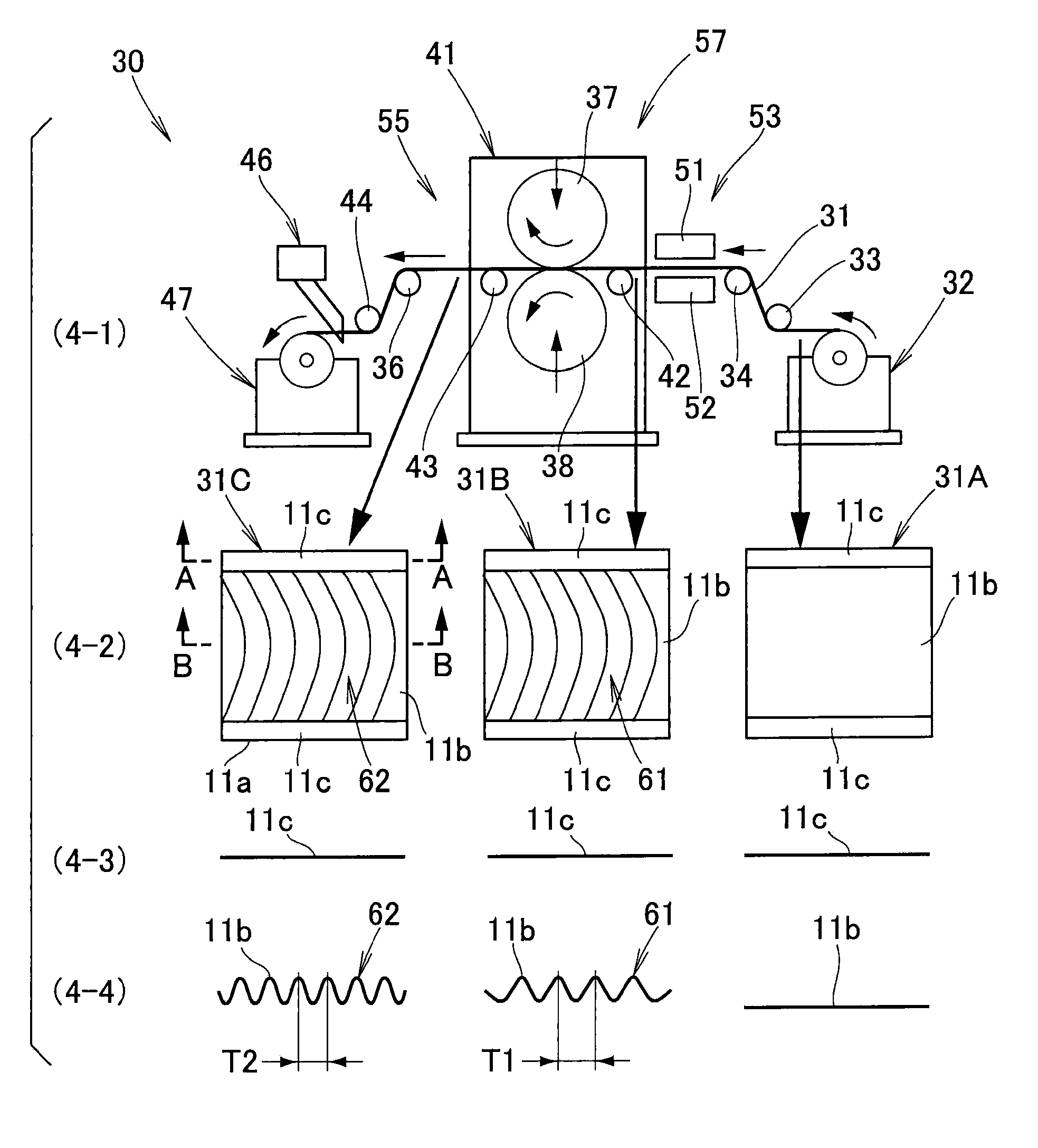
[0010]With the arrangement that the electrode sheet is roll-pressed after the formation, in the longitudinal direction, of the succession of corrugations, the extension produced in the active-material-coated portions of the electrode film due to the roll-pressing can be effectively absorbed in the corrugations, so that no residual stress arises from a difference in extension between the active-material-coated portions and the non-active-material-coated portions of the electrode sheet; thus, the electrode sheet will not curve when it is cut in the longitudinal direction thereof through the width of the sheet. Because almost no extension occurs in the non-active-material-coated portions of the electrode sheet, a thickness change of the electrode sheet can be minimized or prevented. Further, because the battery manufacturing method of the present invention is not arranged to process the side edges of the electrode sheet, it can effectively prevent reduction or lowering of processing accuracy. As a result, it is possible to prevent unwanted breakage and further extension of the positive and negative sheet electrodes when constructing the electrode assembly, and thus achieve an enhanced productivity and product quality of the battery.
[0011]In an embodiment, the above-mentioned step of forming a succession of corrugations forms the corrugations on each of the positive and negative electrode sheets by imparting tension to portions of the electrode sheet located upstream and downstream of roll-pressing rollers when the electrode sheet is to be roll-pressed via the rollers. Namely, as the electrode sheet is fed forward through the rollers, the electrode sheet is pulled forwardly, i.e., downstream, of the rollers. Because the non-active-material-coated portions, having a smaller thickness than the active-material-coated portions, are not sandwiched and detained by the roll-pressing rollers with only the active-material-coated portions sandwiched and detained by the roll-pressing rollers, only the non-active-material-coated portions are moved forward in a sheet feeding direction, so that a succession of corrugations can be produced in the electrode sheet. Thus, the method of the invention can form the corrugations with ease by just imparting tension to the electrode sheet.
[0012]In one embodiment, the step of forming a succession of corrugations forms the corrugations on each of the positive and negative electrode sheets by plastically deforming the active-material-coated portions of the electrode sheet. Such plastically deformation allows the succession of corrugations to be formed with increased ease and accuracy.
[0013]In one embodiment, the step of forming a succession of corrugations forms the corrugations on each of the positive and negative electrode sheets after heating the active-material-coated portions of the electrode sheet. Such heating allows the active-material-coated portions (i.e., electrode active material and electrode film) to be plastically deformed easily, which can even further facilitate the formation of the corrugations.
[0015]In the roll-pressing section, only the active-material-coated portions (i.e., electrode active material and electrode film) are roll-pressed. Namely, the active-material-coated portions of the electrode sheet are roll-pressed and extended, while the non-active-material-coated portions of the electrode sheet are not roll-pressed and extended because they have a smaller thickness than the active-material-coated portions. With the arrangement that the electrode sheet is roll-pressed after the formation, in the longitudinal direction, of the succession of corrugations, the extension produced in the active-material-coated portions of the electrode film due to the roll-pressing can be absorbed in the corrugations, so that no residual stress arises from a difference in extension between the active-material-coated portions and the non-active-material-coated portions of the electrode sheet; thus, the electrode sheet will not curve, due to a difference in extension between the active-material-coated portions and the non-active-material-coated portions, when it is cut in the longitudinal direction thereof through the width of the sheet. Because almost no extension occurs in the non-active-material-coated portions of the electrode sheet, the thickness change of the electrode sheet, particularly the non-active-material-coated portions, can be minimized. Further, because the battery manufacturing apparatus of the invention is not arranged to process the side edges of the electrode sheet, it can effectively prevent reduction or lowering of processing accuracy. As a result, it is possible to prevent unwanted breakage and further extension of the positive and negative sheet electrodes when constructing the electrode assembly, and thus achieve an enhanced productivity and product quality of the battery.

Problems solved by technology

Further, in some conventional electrode sheet manufacturing apparatus, pressing, slitting and winding steps of an electrode sheet process edges of the electrode sheet, and thus, if the edges of the electrode sheet has a corrugated shape, it tends to be difficult to accurately position the electrode sheet at a predetermined position, which results in a reduced processing accuracy.

Method used


Image

  • Battery manufacturing method and apparatus
  • Battery manufacturing method and apparatus
  • Battery manufacturing method and apparatus

Examples


Embodiment Construction

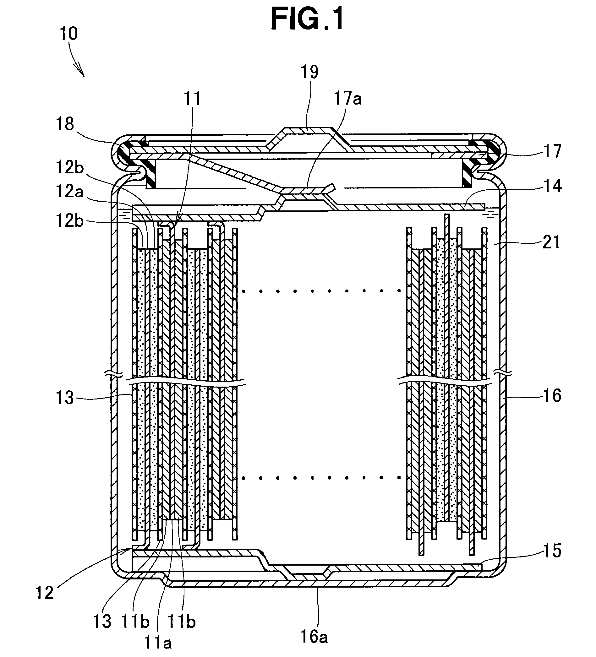
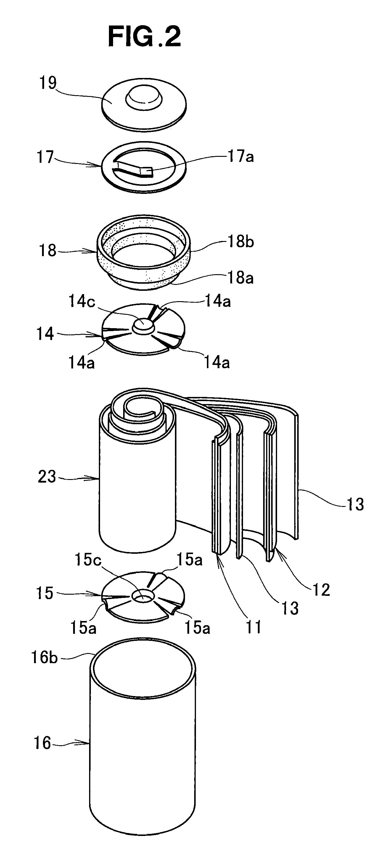
[0033]Reference is now made to FIG. 1 showing in section a battery manufactured in accordance with the present invention. The battery 10 includes: positive and negative sheet electrodes 11 and 12 each having its opposite surfaces coated with an electrode active material; separators 13 disposed between the positive and negative sheet electrodes 11 and 12 etc.; a current collector 14 held in contact with an upper end portion (i.e., non-active-material-coated portion) of the positive sheet electrode 11; a current collector 15 held in contact with a lower end portion (i.e., non-active-material-coated portion) of the negative sheet electrode 12; a conductive case 16 having accommodated therein the positive and negative sheet electrodes 11 and 12, separators 13 and disk-shaped current collector 14 and 15; a conductive plate 17 pressing the positive and negative sheet electrodes 11 and 12, separators 13 and current collector 14 and 15 against the bottom of the case 16; a lid 19 swaged, via...


PUM

PropertyMeasurementUnit
tensionaaaaaaaaaa
elongationaaaaaaaaaa
thicknessaaaaaaaaaa

Abstract

For manufacturing a battery including positive and negative sheet electrodes formed from positive and negative electrode sheets each having active-material-coated portions on opposite surfaces, except for opposite surfaces of one side edge portion, of the sheet and non-active-material-coated portions on the opposite surfaces of the one side edge portion, a method includes: forming a succession of corrugations on each of the sheets, having the coated portions provided thereon, in a longitudinal direction of the sheet; roll-pressing each of the sheets having the corrugations formed thereon; constructing an electrode assembly of the positive and negative sheet electrodes with a separator interposed therebetween; and connecting current collectors to the non-coated portions of the sheet electrodes.

Description

FIELD OF THE INVENTION[0001]The present invention relates to an improvement in a battery manufacturing method and apparatus.BACKGROUND OF THE INVENTION[0002]There have been known batteries including a roll-shaped electrode assembly formed by winding sheet-shaped positive and negative electrodes into a roll shape together with a separator. In manufacturing positive and negative electrodes of these conventionally-known batteries, the positive and negative electrodes would be undesirably deformed due to a difference in extension (or elongation) between a portion coated with an electrode active material and other portions not coated with the electrode active material, as detailed below with reference to FIG. 14 hereof.[0003]FIG. 14 is a view explanatory of a conventionally-known battery manufacturing method. Namely, an electrode sheet 203 having a coated portion 201 coated with an electrode active material 200 and non-coated portions 202 not coated with the electrode active material 200...

Claims


Application Information

Patent Timeline
Patent Type & Authority Applications(United States)
IPC IPC(8): H01M2/00H01M4/04H01M10/0587
CPCH01M4/02H01M4/0404H01M4/0435Y10T29/53139H01M2004/025Y10T29/4911H01M10/0409Y02E60/10Y02P70/50
Inventor IKEDA, KOHEITAKEHARA, TETSUHIROMORIWAKI, TOMONORIFUNAKI, MITSUHIRO
Owner HONDA MOTOR CO LTD
Learn More