
Steam vacuum cleaner

a vacuum cleaner and steam technology, applied in the direction of vacuum cleaners, carpet cleaners, cleaning filter means, etc., can solve the problems of large contact area with the floor, bulky and wide related art steam vacuum cleaners, and difficult cleaning under the bed or the couch, so as to reduce the air discharge rate

Inactive Publication Date: 2009-04-23
HAAN GYUNG HEE
View PDF3 Cites 7 Cited by
  • Summary
  • Abstract
  • Description
  • Claims
  • Application Information

AI Technical Summary

Benefits of technology

[0010]To address deficiencies of the related art, it is, therefore, an object of the present invention to provide a steam vacuum cleaner capable of filtering fine dust and at the same time reducing air discharge rate to prevent the dust from scattering by the discharged air flow.
[0012]The steam vacuum cleaner with this configuration is advantageously used for filtering fine dust and reducing air discharge rate at the same time such that the dust may not be scattered by the discharged air flow.
[0013]In an exemplary embodiment, the filter cover is composed of a cover plate provided with an exhaust hole, a detachable projection formed at the upper and lower faces of the cover plate to be lodged into a locking groove formed at the upper and lower faces inside the exhaust groove, and an operation unit for operating the detachable projection. Since both the detachable projection and the locking groove are formed inside the exhaust groove, a structure like a recessed groove is not seen from outside and an aesthetic value of the cleaner is therefore enhanced.

Problems solved by technology

Because of this, the main body of the related art steam vacuum cleaner has a certain height, making it difficult to clean under the bed or the couch.
Besides, the main body of the related art steam vacuum cleaner is bulky and wide such that its contact area with the floor is large.
As the contact resistance requires a bit more force to move (e.g., push and pull) the cleaner, a user feels more difficult to clean with this type of cleaner.
In addition, since the dust collection bin only has a function of collecting dust, the filter installed at a suction opening of the motor is often clogged up.
This shortens the cleaning cycle of the filter and another inconvenience for the user is posed.
Still another adverse effect of the related art steam vacuum cleaner is that when in use for steam cleaning and / or vacuum cleaning, it is highly possible that the sucked-up steam enters the motor and causes an electrical short.
In addition, whether the dust collection bin is installed inside or outside the main body, its particular shape makes it difficult to take out.
Therefore, its low cooling efficiency had to be compensated by installing a motor with a relatively large capacity.

Method used


Image

  • Steam vacuum cleaner
  • Steam vacuum cleaner
  • Steam vacuum cleaner

Examples


Embodiment Construction

[0030]Hereinafter, preferred embodiments of the present invention will be set forth in detail with reference to the accompanying drawings so that those skilled in the art can easily carry out the invention.

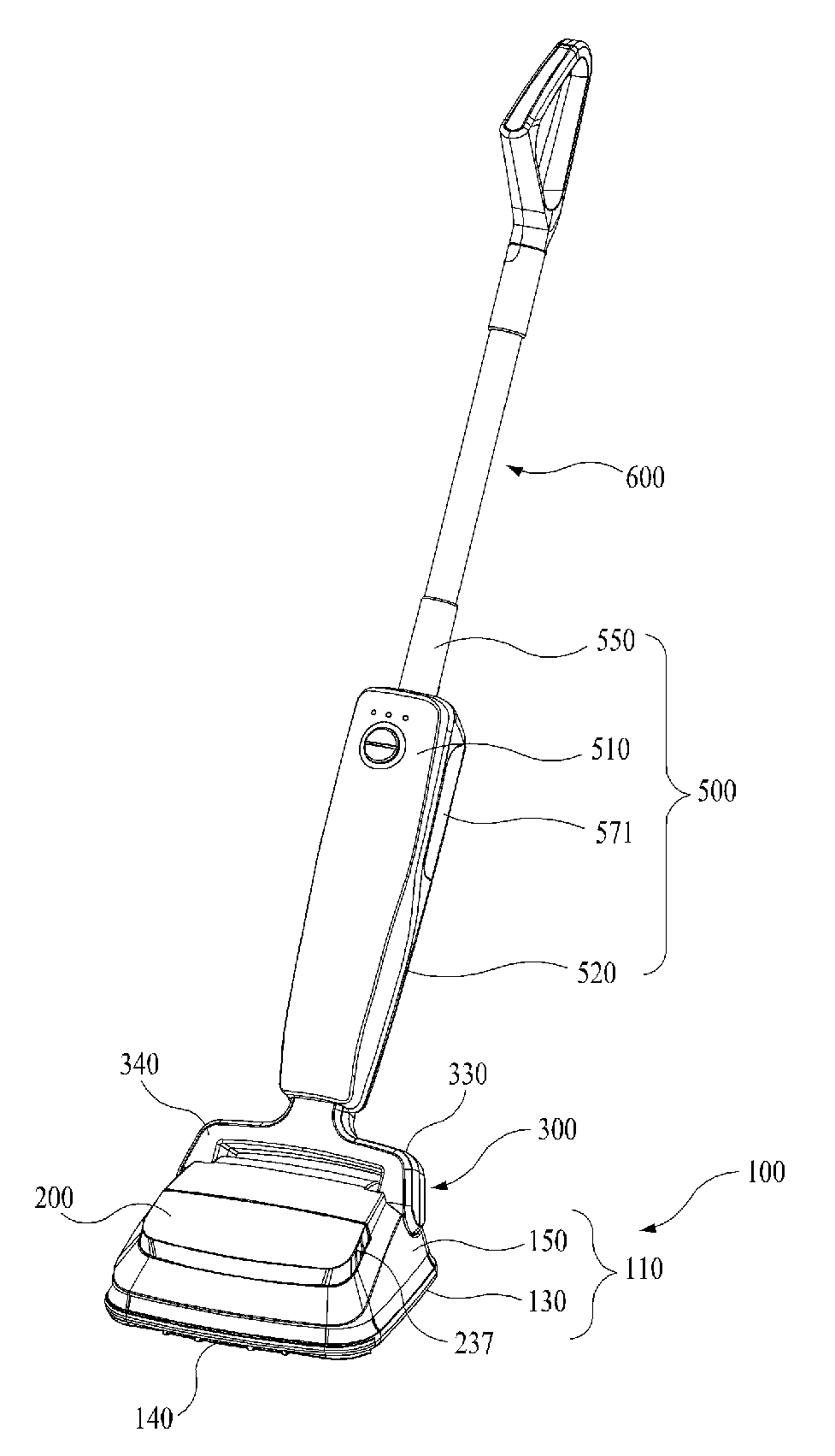
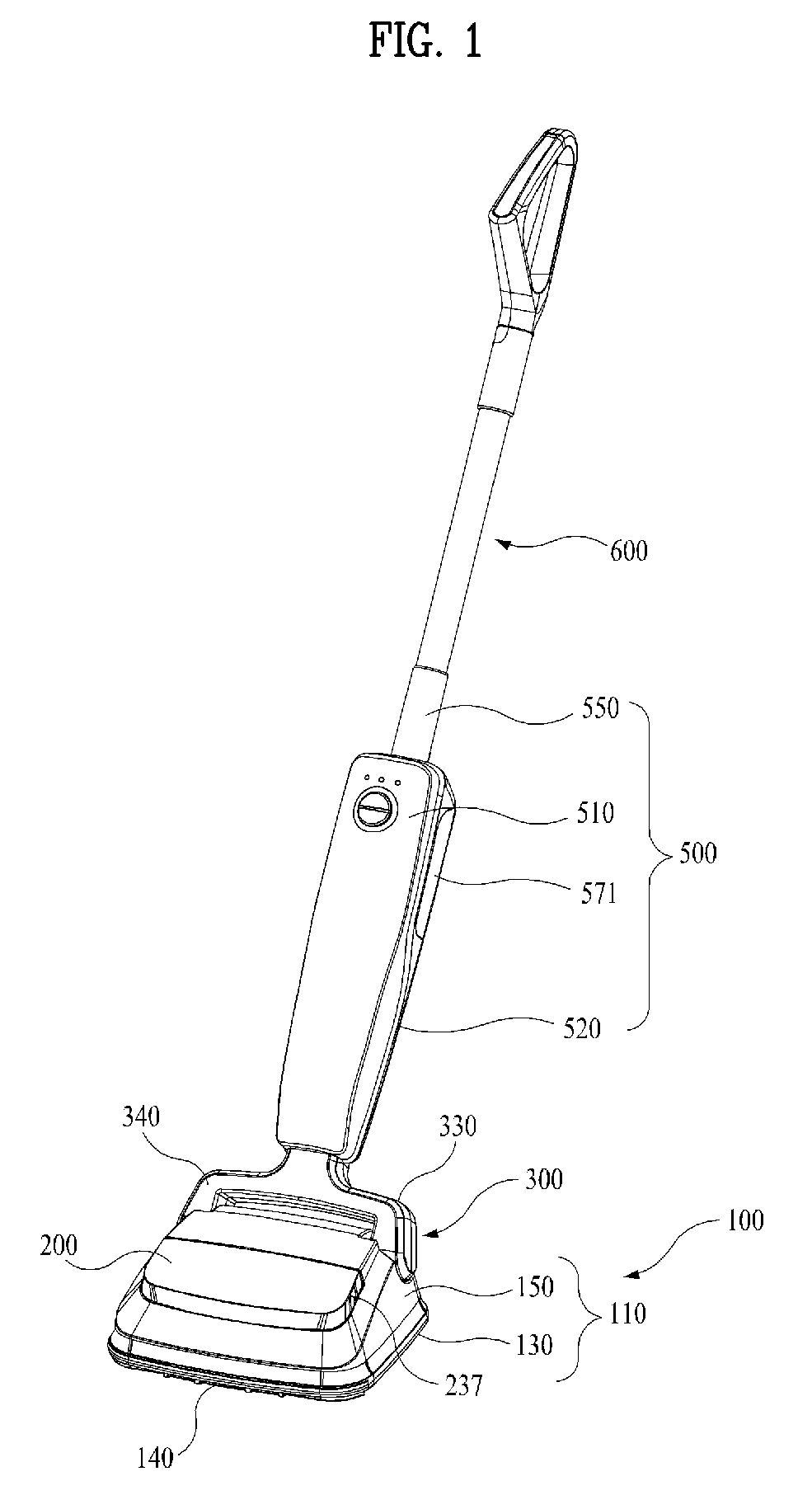
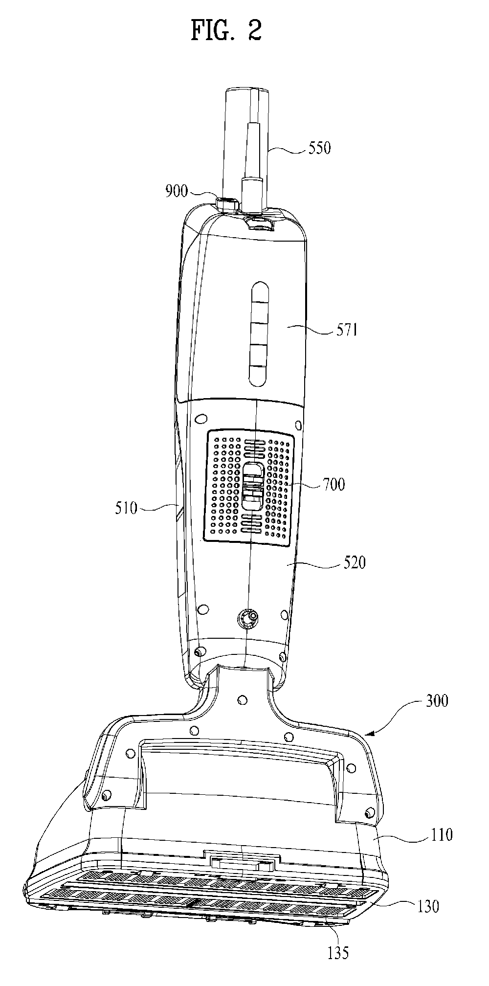
[0031]FIG. 1 is a front perspective view of a steam vacuum cleaner according to a preferred embodiment of the present invention, and FIG. 2 is a rear perspective view of FIG. 1.

[0032]Referring to the outer appearance shown in FIGS. 1 and 2, the steam vacuum cleaner of this embodiment is largely constituted by a base assembly 100, a main assembly 500, and a neck assembly 300 connecting between the base assembly 100 and the main assembly 500.

[0033]The min assembly 500 has a pipe 550 (to be described) to which a length-adjustable mop handle 600 is connected in a detachable manner. The mop handle 600 is composed of a telescopic stick and a handle.

[0034]The base assembly 100, as depicted in FIG. 3, FIG. 4, and FIG. 7, is composed of a main body 110 including a bedplate 130 and an upper...


PUM


Abstract

A steam vacuum cleaner includes a main assembly functioning as a mopstick, and the main assembly has an exhaust duct with a built-in filter formed at a rear face thereof.

Description

CROSS-REFERENCE(S) TO RELATED APPLICATIONS[0001]The present invention claims priority of Korean patent application number 10-2007-0032448, filed on Apr. 2, 2007, which is incorporated by reference in its entirety.BACKGROUND OF THE INVENTION[0002]The present invention relates to a steam vacuum cleaner including a main assembly that functions as a mopstick, the main assembly having an exhaust duct with a built-in filter formed at a rear face thereof.[0003]Korean utility model registration Nos. 20-0404402 and 20-0413652 and Korean patent application publication No. 10-2007-0027895 disclosed a steam vacuum cleaner where a dust collection bin, a suction motor, and a steam generator are all installed in the main body. Because of this, the main body of the related art steam vacuum cleaner has a certain height, making it difficult to clean under the bed or the couch.[0004]Besides, the main body of the related art steam vacuum cleaner is bulky and wide such that its contact area with the flo...

Claims


Application Information

Patent Timeline
IPC IPC(8): A47L7/00
CPCA47L7/0038A47L7/0009A47L11/34A47L9/10A47L11/20
Inventor HAAN, GYUNG-HEE
Owner HAAN GYUNG HEE
Learn More