
Split scrolling illumination for light modulator panels

a technology of light modulator and scrolling light band, which is applied in the field of display devices, can solve the problems that the illumination method with scrolling light band as described above is no longer applicable, and achieve the effect of high resolution images

Inactive Publication Date: 2009-04-16
BARCO NV
View PDF7 Cites 6 Cited by
  • Summary
  • Abstract
  • Description
  • Claims
  • Application Information

AI Technical Summary

Benefits of technology

[0013]It is an object of embodiments of the present invention to provide good apparatus or methods for displaying images, e.g. high resolution images.
[0035]It is an advantage of embodiments of the present invention that limited, e.g. reduced, smearing may be obtained.
[0036]It is a further advantage of embodiments of the present invention that display systems with low latency are obtained.

Problems solved by technology

As a consequence the known illumination methods with a scrolling light band as described above are no longer applicable.

Method used


Image

  • Split scrolling illumination for light modulator panels
  • Split scrolling illumination for light modulator panels
  • Split scrolling illumination for light modulator panels

Examples


Embodiment Construction

[0055]The present invention will be described with respect to particular embodiments and with reference to certain drawings but the invention is not limited thereto but only by the claims. The drawings described are only schematic and are non-limiting. In the drawings, the size of some of the elements may be exaggerated and not drawn on scale for illustrative purposes. The dimensions and the relative dimensions do not correspond to actual reductions to practice of the invention.

[0056]Furthermore, the terms first, second, third and the like in the description and in the claims, are used for distinguishing between similar elements and not necessarily for describing a sequence, either temporally, spatially, in ranking or in any other manner. It is to be understood that the terms so used are interchangeable under appropriate circumstances and that the embodiments of the invention described herein are capable of operation in other sequences than described or illustrated herein.

[0057]More...


PUM


Abstract

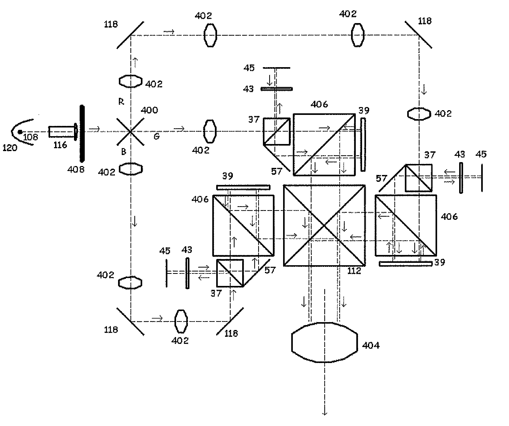
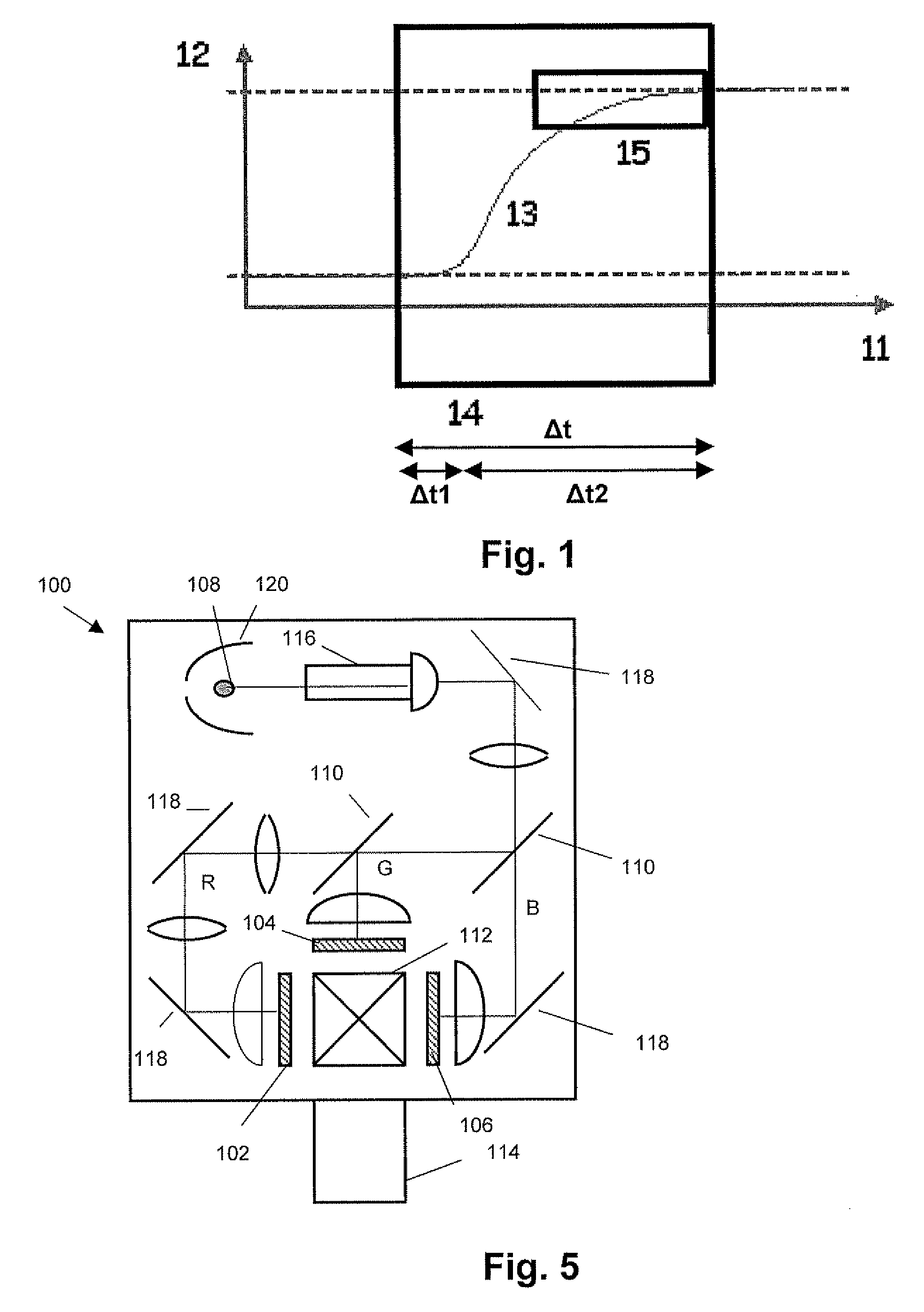
A display system in accordance with embodiments of the present invention comprises illumination means (108) for providing a light beam; at least one colour channel (R, G, B), each colour channel being adapted for providing at least part of the light beam to a spatial light modulator panel (39) comprising at least a first and a second zone; the spatial light modulator panel (39) being for selectively modulating an impinging beam of light to form an image light beam. The display system further comprises splitting means (37) for splitting the at least part of the light beam so that a split light beam is provided on the spatial light modulator panel (39), the split light beam comprising at least a first and a second sub-beam, and driving means (408) for driving the first and second sub-beams such that the first sub-beam scrolls over the first zone and the second sub-beam scrolls over the second zone.The present invention also provides a corresponding method.

Description

TECHNICAL FIELD OF THE INVENTION[0001]The present invention relates to the field of display devices with one or more spatial light modulator panels, such as e.g. liquid crystal device (LCD), liquid crystal on silicon (LCOS) devices or digital mirror devices (DMD), in particular spatial light modulator panels which are driven by simultaneously writing data to different portions spread over different zones of the light modulator panel, for example high resolution spatial light modulator panels. More particularly, the present invention relates to image display apparatus and methods for improving the display of moving images.BACKGROUND OF THE INVENTION[0002]Almost all common projection devices are based on one of the basic image modulator devices. Where the old technology using Cathode Ray Tubes (CRT) is almost completely outdated, the liquid crystal light valves (LCDs) and is the digital micro-mirror devices (DMDs) currently are used in most of the projectors. During the last years, a ...

Claims


Application Information

Patent Timeline
Patent Type & Authority Applications(United States)
IPC IPC(8): G03B21/00
CPCG09G3/3666G09G3/367H04N9/315G09G2320/0261H04N9/3117G09G2310/0283
Inventor MALFAIT, KOEN
Owner BARCO NV
Learn More