
Apparatus, Systems and Methods For Facilitating Ignition Of A Solid Fuel

a technology of apparatus and solid fuel, which is applied in the direction of lighting and heating apparatus, household stoves or ranges, combustion processes, etc., can solve the problems of unsatisfactory resolution of several important problems, disadvantaged starters, and known undesirable smells and aftertastes, so as to facilitate efficient, reliable and safe approaches to control fire-based activities , the effect of facilitating the ignition of solid fuel

Inactive Publication Date: 2009-04-16
KAYE RICHARD G
View PDF3 Cites 22 Cited by
  • Summary
  • Abstract
  • Description
  • Claims
  • Application Information

AI Technical Summary

Benefits of technology

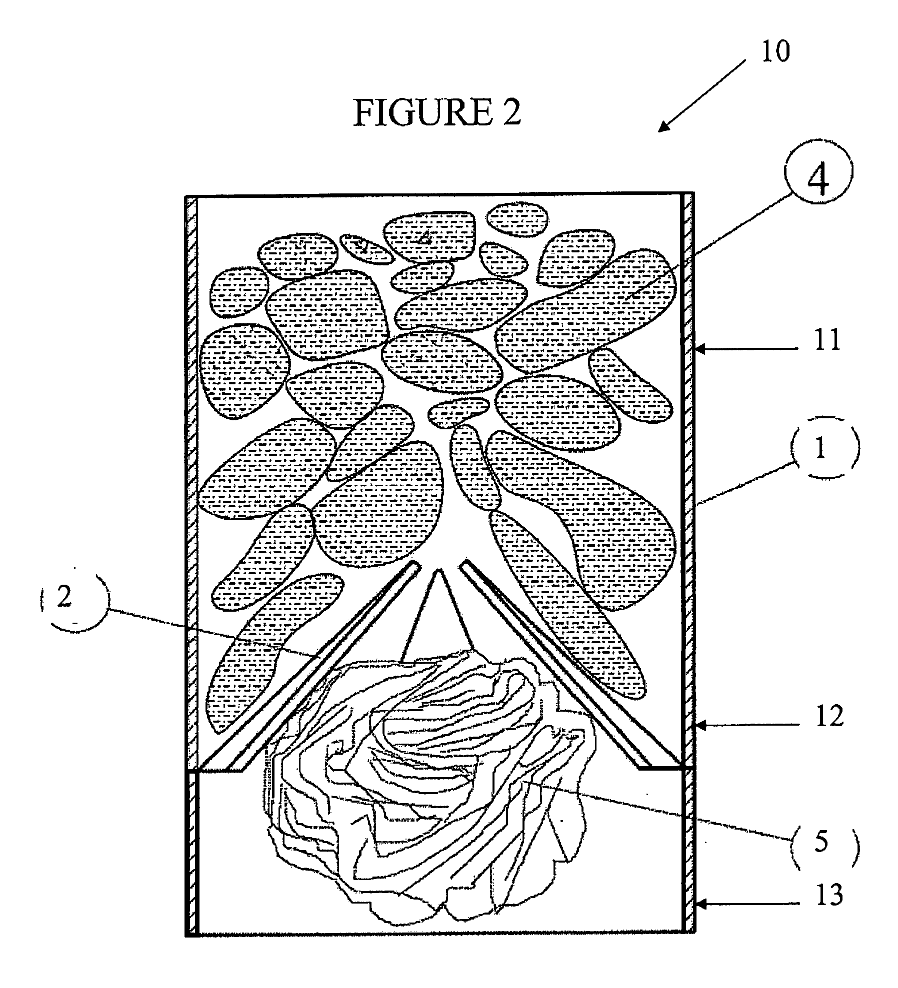
[0012]The present disclosure provides advantageous apparatus, systems and methods for facilitating ignition of solid fuel. More particularly, the present disclosure provides apparatus, systems and methods that facilitate ignition of a solid fuel using a combustible, self-consuming chimney starter. The disclosed combustible chimney starter and associated ignition methodologies facilitate efficient, reliable and safe approaches for controlled fire-based activities, e.g., grilling of foodstuffs. Moreover, the present disclosure offers significant advantages with respect to packaging, portability and convenience.
[0013]Apparatus and systems disclosed herein generally include a container defined by one or more walls that define top and bottom compartments or regions. Solid fuel is positioned or deposited in the top compartment or region and kindling material may be positioned or deposited in the bottom compartment or region. A divider is generally defined between the top compartment / region and the bottom compartment / region. Such divider is porous or otherwise structured so as to permit air / gas flow therethrough and / or thereby. Such air / gas flow allows for efficient oxygenation and / or ventilation of the solid fuel positioned in the top compartment / region. Moreover, the divider is advantageously configured and dimensioned to support the solid fuel in the top compartment / region.
[0016]In exemplary embodiments of the disclosed apparatus / system, one or more of the wall(s) that define the chimney starter container / enclosure are pierced, lanced or otherwise cut so as form one or more flaps. Generally, a multiplicity of flaps are formed from the wall(s) of the container / enclosure and such flaps are folded / pivoted inwardly relative to the center of the container / enclosure so as to define / form the divider. Exemplary flaps are configured and dimensioned so as to cooperate, when folded / pivoted inward, to support the solid fuel. Thus, the flaps may be interspersed / overlapping so as to provide enhanced support.
[0017]In exemplary embodiments of the disclosed chimney starter apparatus / system, the flaps are pre-folded to as to form a divider. In such exemplary embodiments, solid fuel may be pre-packaged and / or pre-positioned in the top compartment / region (e.g., a bag of charcoal may be included in the top compartment / region) prior to delivery to a potential user. In other exemplary embodiments of the disclosure, the flaps may be defined / formed (e.g., through lancing of the wall(s) of the container), but not yet folded inward to define / form the divider. In such exemplary implementations, an apparatus / system user may be deflect / fold the flaps inwardly to define / form the divider. Thereafter, charcoal or other suitable solid fuel may be positioned on the divider for sustained ignition, as described herein. Additional structures / components may be provided in conjunction with the inwardly deflected / folded flaps for purposes of the disclosed divider, e.g., an overlaying combustible support that further facilitates positioning of the solid fuel in the top region / compartment. The flaps may be positioned in a substantially horizontal orientation relative to the vertical wall(s) of the chimney starter apparatus / system or may be angled upwardly relative to such vertical wall(s), e.g., at an angle of about 5 to 20° relative to a horizontal plane that is orthogonal to the vertical wall(s) of the apparatus / system.

Problems solved by technology

Lighter fluids, however, are known to introduce undesirable smells and aftertastes to the solid fuel being ignited, and subsequently to food cooked using such solid fuel.
Electrical coils are similarly disadvantaged due to an inherently long ignition time and a general encumbrance on portability (e.g., requiring electricity to operate).
Despite these clear advantages, current embodiments of chimney starters have several important disadvantages which have yet to be adequately solved.
This transfer of heated fuel is inherently hazardous to those nearby as well having a propensity to cause damage to nearby surfaces.
Indeed, ash, sparks and pieces of hot fuel may be spilled during the transfer process, potentially damaging surrounding surfaces, risking fires and / or potentially burning the user.
Furthermore, once the fuel has been transferred, the apparatus used to ignite the fuel is often times extremely hot and therefore hazardous.
These steps are time-consuming, energy-consuming and space-consuming processes.
Furthermore, the chimney starters are designed for subsequent cleaning and storage, with the associated disadvantages inherent therein.
For one, the apparatus lacks a compartment for kindling material, making ignition of the charcoal difficult.
Furthermore, once the apparatus is removed, the charcoal may shift, causing ember and sparks to fly towards the user.
Thus, the removal step presents a potentially hazardous and uncomfortable situation for the user.
The disclosed apparatus, however, does not promote an advantageous flue effect.
Furthermore, there is no separate compartment for kindling material.
Indeed, the disclosed structure resembles a bag with a raised bottom, with the ignition limitations inherent therein.
After sustained ignition of the solid fuel is achieved, the apparatus / system (including specifically the side wall(s) and the divider) generally collapse and are consumed in flame.

Method used


Image

  • Apparatus, Systems and Methods For Facilitating Ignition Of A Solid Fuel
  • Apparatus, Systems and Methods For Facilitating Ignition Of A Solid Fuel
  • Apparatus, Systems and Methods For Facilitating Ignition Of A Solid Fuel

Examples


Embodiment Construction

)

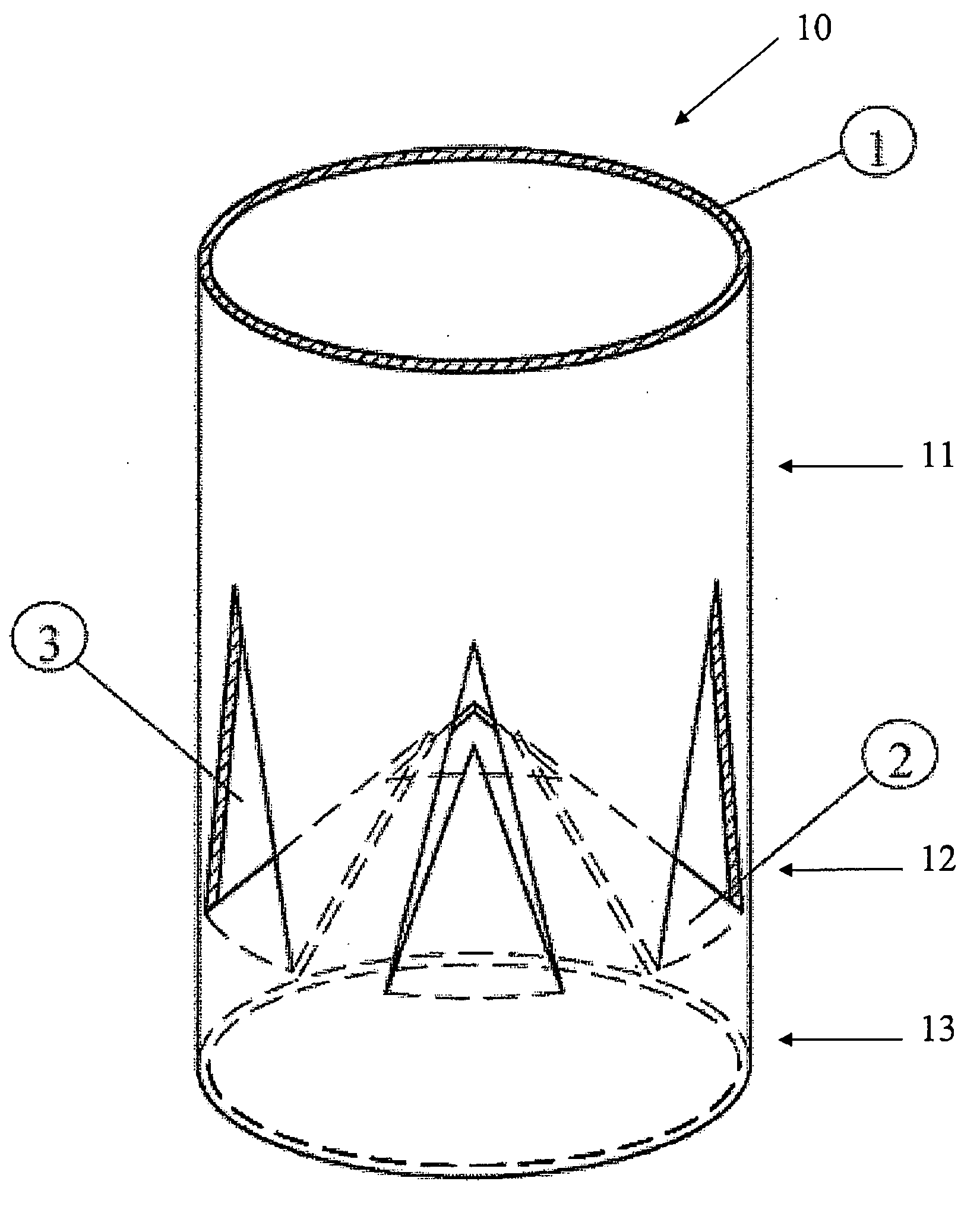
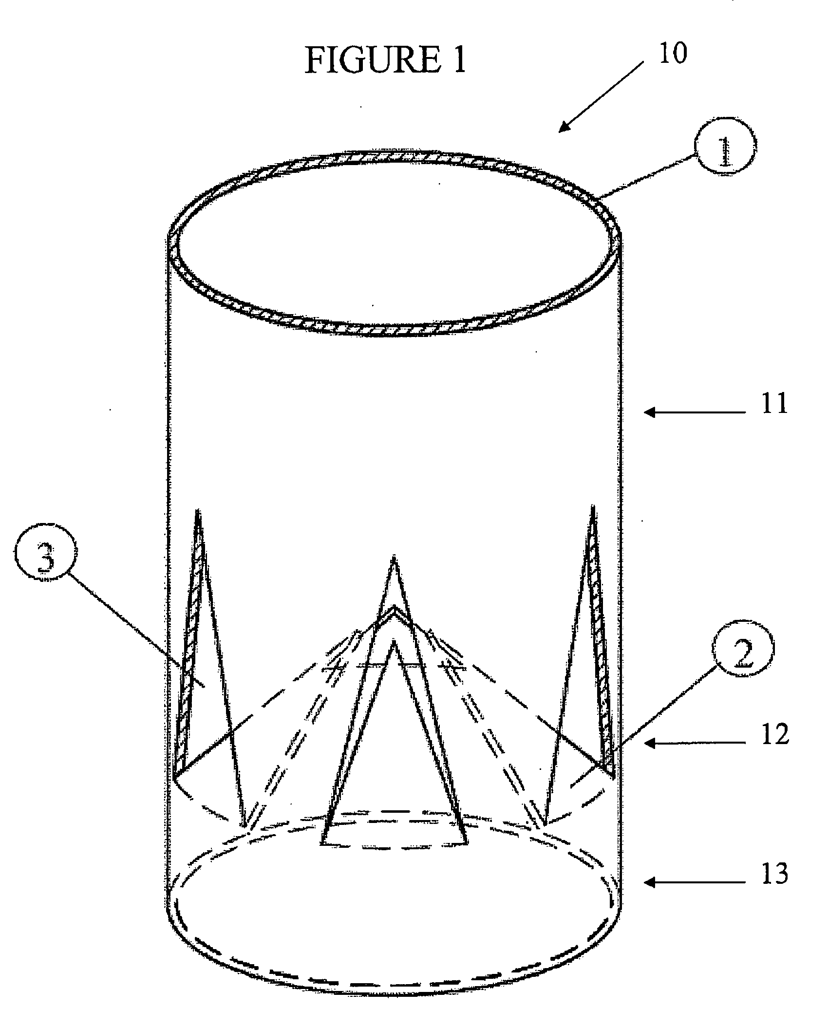
[0028]As noted above, the present disclosure provides apparatus, systems and methods that facilitate sustained ignition of solid fuel. With initial reference now to FIG. 1, a perspective view of an exemplary apparatus 10 according to the present disclosure is schematically depicted. The apparatus 10 defines an upper compartment / region 11 and a lower compartment / region 13. Upper and lower compartments / regions 11, 13 are separated by a divider 12. In general, apparatus 10 is defined by one or more side walls.

[0029]In the particular embodiment depicted in FIG. 1, apparatus 10 is defined by a single side wall 1. Side wall 1 is configured and dimensioned such that the apparatus 10 defines a substantially tubular structure. Apparatus 10, however, may include any number of side walls and may be configured to define substantially any geometry provided that an internal conduit / passage is defined for function as a flue. Exemplary side wall configurations include, but are not limited to, a ci...


PUM


Abstract

A charcoal starter is provided that is fully consumable through combustion. The starter takes the form of a container that includes one or more walls that define a top and bottom compartment. Solid fuel is deposited in the top compartment and kindling material is deposited in the bottom compartment. The divider allows for oxygenation and ventilation while also supporting the solid fuel in the top compartment. The starter is generally composed of a cardboard or other flammable, non-toxic material. The starter is configured such that solid fuel is supported in the top compartment for a period of time after the kindling material is lit and thereafter collapses and is completely consumed. Associated methods for igniting solid fuel, e.g., charcoal, are also disclosed.

Description

BACKGROUND[0001]1. Technical Field[0002]The present disclosure relates to apparatus, systems and methods for facilitating ignition of a solid fuel. More particularly, the present disclosure relates to apparatus, systems and methods that employ a chimney or flue effect in order to ignite solid fuel, e.g. charcoal, briquettes and the like. The present disclosure also relates to portable and self-consuming apparatus / systems for facilitating the ignition of a solid fuel. Exemplary applications of the apparatus, systems and methods disclosed herein are primarily directed towards (although explicitly not limited to) ignition of charcoal and / or briquettes for grilling or other cooking purposes.[0003]2. Background Art[0004]It is commonly known that some solid fuels, e.g., charcoal and briquettes, require the application of an external heat source, e.g., a flame, in order to be ignited. To this end, many apparatus, systems and methods have been devised in order to cause and / or facilitate suc...

Claims


Application Information

Patent Timeline
Patent Type & Authority Applications(United States)
IPC IPC(8): F24B3/00A47J37/00F23Q13/00
CPCA47J37/079
Inventor KAYE, RICHARD G.
Owner KAYE RICHARD G
Learn More