
CVT control system having variable power source speed

Inactive Publication Date: 2009-04-02
CATERPILLAR INC
View PDF26 Cites 22 Cited by
  • Summary
  • Abstract
  • Description
  • Claims
  • Application Information

AI Technical Summary

Benefits of technology

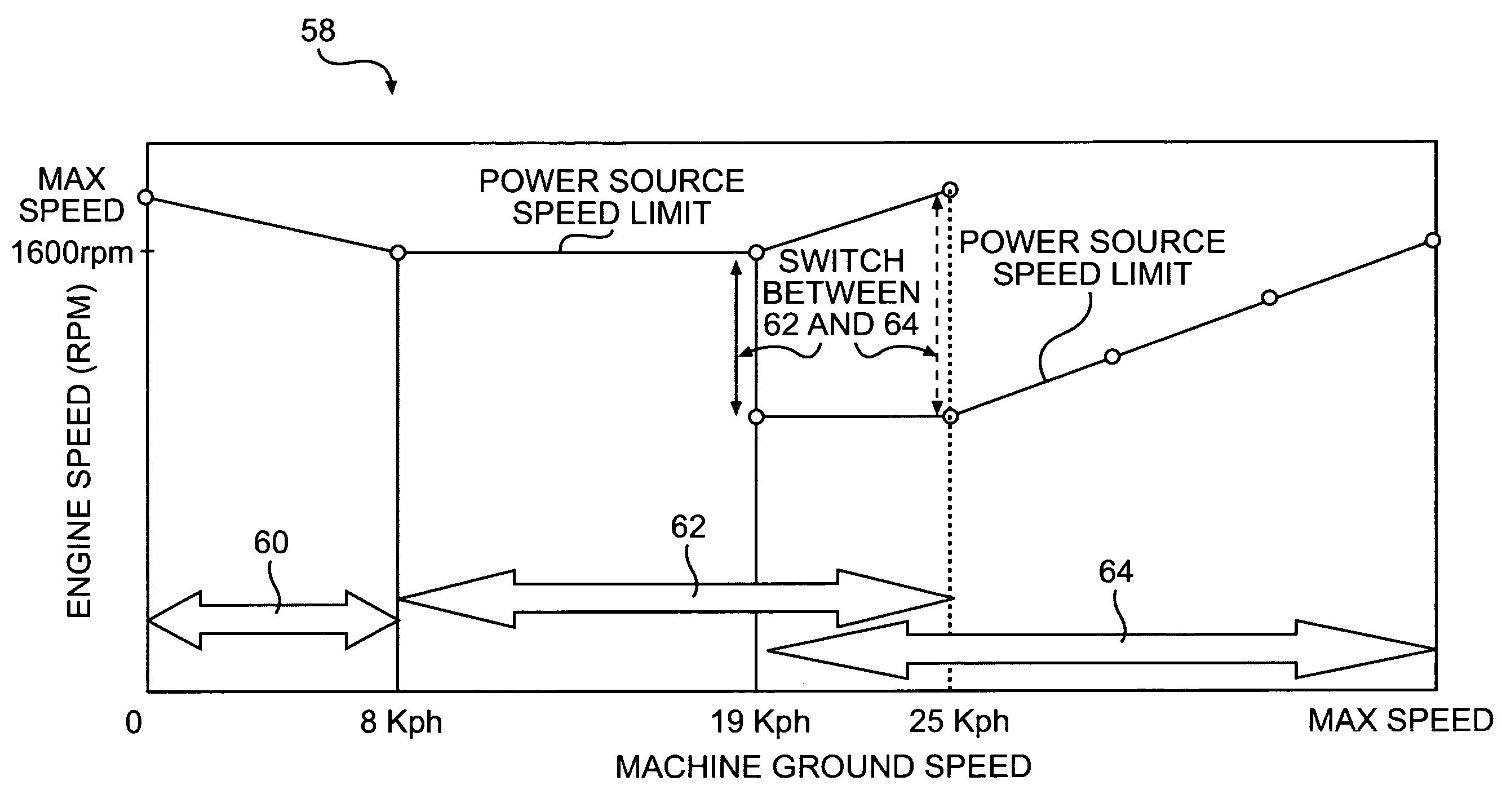
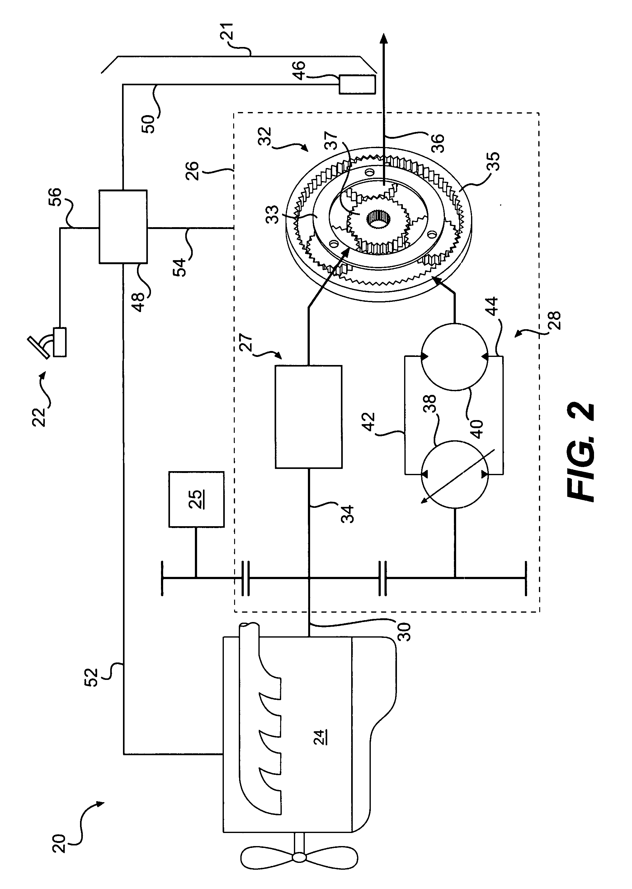
[0007]In one aspect, the present disclosure is directed to a powertrain control system. The powertrain control system may include a power source and a CVT coupled to an output of the power source. The powertrain control system may further include a controller in communication with the power source and the CVT. The controller may include a map with a plurality of speed modes, and, for at least one of the plurality of speed modes, the controller may be configured to vary an actual power source speed bas

Problems solved by technology

Operating outside of this range may increase fuel consumption and / or decrease responsiveness.
Although the machine of the '374 patent may help the motor remain responsive while preventing potential damage to the motor and transmission, it may not provide for efficient operation and control of the engine under all conditions.
By only controlling the motor speed, the control system of the '374 patent may allow the engine to operate at an inefficient and / or unresponsive engine speed (i.e., either too low or too high) for the presently occurring transmission gear ratio, work implement conditions, and load conditions.

Method used


Image

  • CVT control system having variable power source speed
  • CVT control system having variable power source speed
  • CVT control system having variable power source speed

Examples


Embodiment Construction

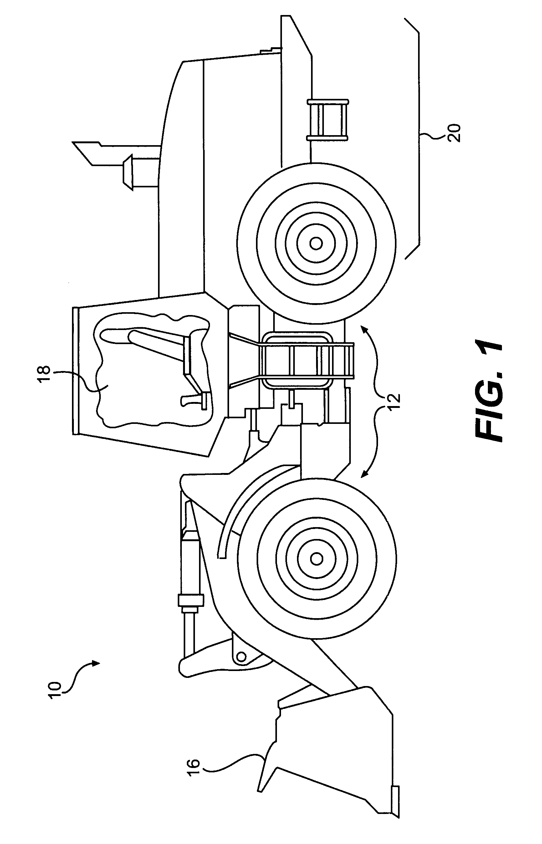
[0012]FIG. 1 illustrates an exemplary machine 10. Machine 10 may be a mobile vehicle that performs some type of operation associated with an industry such as mining, construction, farming, transportation, or any other industry known in the art. For example, machine 10 may be an earth moving machine, such as a wheel loader, an excavator, a backhoe, a motor grader, or any other suitable earth moving machine known in the art. Alternatively, machine 10 may be a load carrying vehicle, a marine vessel, a passenger vehicle, or any other suitable operation-performing machine. Machine 10 may include one or more traction devices 12, a work implement 16, an operator station 18, and a powertrain 20.

[0013]Traction devices 12 may include one or more wheels located on each side of machine 10 (only one side shown) configured to allow translational motion of machine 10. Alternatively, traction devices 12 may include tracks, belts, or other traction devices known in the art. Any of traction devices 1...


PUM


Abstract

A powertrain control system is disclosed. The powertrain control system may have a power source and a CVT coupled to an output of the power source. The powertrain control system may further have a controller in communication with the power source and the CVT. The controller may have a map with a plurality of speed modes, and, for at least one of the plurality of speed modes, the controller may be configured to vary an actual power source speed based on at least one of a CVT output speed or a ground speed.

Description

TECHNICAL FIELD [0001]The present disclosure relates generally to a control system for a machine with a CVT transmission and, more particularly, to a control system for varying a power source speed based on a CVT output speed.BACKGROUND [0002]Machines such as, for example, on-highway vocational vehicles, off-highway haul trucks, wheel loaders, motor graders, and other types of heavy machinery are used for a variety of tasks. These machines generally include a power source, which may embody, for example, an engine, such as a diesel engine, a gasoline engine, or a gaseous fuel-powered engine that provides the power required to complete these tasks. The power produced by the power source may be transmitted through a transmission, such as, for example, a continuously variable transmission (“CVT”), to one or more ground engaging devices in order to propel the machine.[0003]Machine control systems are often used to coordinate and regulate operation of the power source and CVT to improve t...

Claims


Application Information

Patent Timeline
IPC IPC(8): G06F17/00F16H61/46F16H61/465F16H61/47
CPCB60W10/06B60W30/1882B60W2710/0644B60W10/101F16H61/465F16H61/47F16H2037/088F16H47/04
Inventor HUBBARD, MILTON CARTERHOFF, BRIAN DOUGLASRETTIG, MARK EDWARDJURICAK, STEVEN JAMES
Owner CATERPILLAR INC
Learn More