
System and Method for Manufacturing a Swallowable Sensor Device

a sensor device and manufacturing method technology, applied in the field of medical diagnostics, can solve the problems of increasing the incidence of cardiac problems in women, and the size of conventional swallowable sensor devices

Inactive Publication Date: 2009-04-02
INNURVATION
View PDF18 Cites 145 Cited by
  • Summary
  • Abstract
  • Description
  • Claims
  • Application Information

AI Technical Summary

Problems solved by technology

There is a rising incidence of cardiac problems for women (the number one cause of death for women).
However, conventional swallowable sensor devices have several drawbacks.
One drawback of conventional swallowable sensor devices is that they are quite large.
In fact, conventional swallowable sensor devices are so large that a portion of the patient population cannot even swallow these devices.
Even if a patient could swallow a conventional swallowable sensor device, its large size could cause it to become lodged in the patient's gastrointestinal tract, which would require surgery to remove.
Another problem with conventional swallowable sensor devices is that they use a radio frequency (RF) signal platform to communicate with external entities.
The extent to which RF signals cause harm to human tissue is not fully understood.
The potential for harm only increases as the source of the RF signals comes closer to human tissue.
As a result, many patients are apprehensive about ingesting conventional swallowable sensor devices.

Method used


Image

  • System and Method for Manufacturing a Swallowable Sensor Device
  • System and Method for Manufacturing a Swallowable Sensor Device
  • System and Method for Manufacturing a Swallowable Sensor Device

Examples


Embodiment Construction

I. Overview

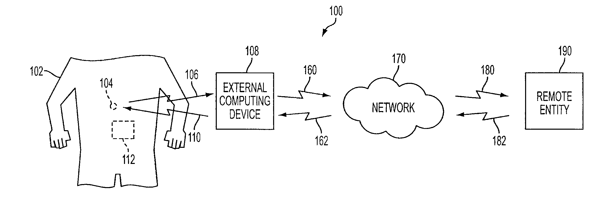
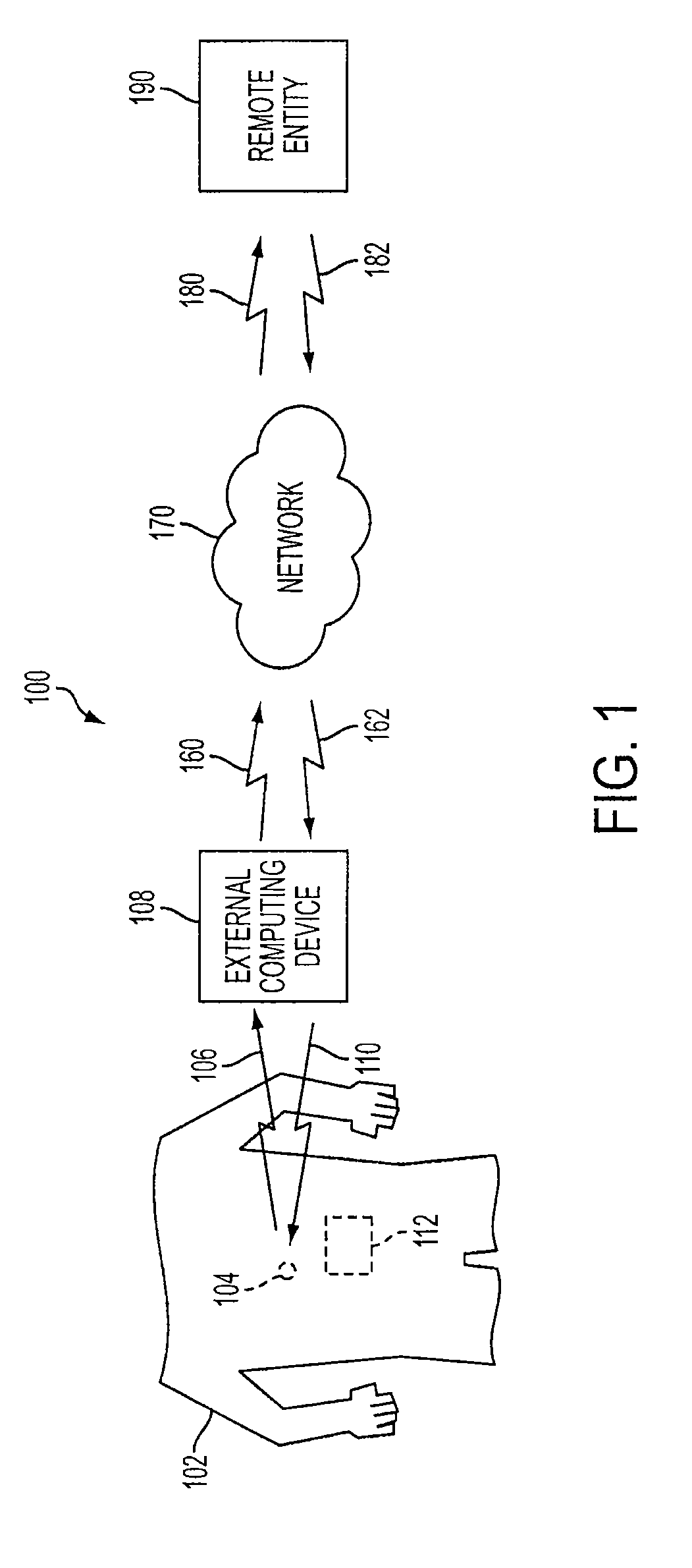
[0027]Described herein are methods and systems for manufacturing a swallowable sensor device, and applications thereof. In the specification, references to “one embodiment,”“an embodiment,”“an example embodiment,” etc., indicate that the embodiment described may include a particular feature, structure, or characteristic, but every embodiment may not necessarily include the particular feature, structure, or characteristic. Moreover, such phrases are not necessarily referring to the same embodiment. Further, when a particular feature, structure, or characteristic is described in connection with an embodiment, it is submitted that it is within the knowledge of one skilled in the art to affect such feature, structure, or characteristic in connection with other embodiments whether or not explicitly described.

[0028]A swallowable sensor device manufactured in accordance with an embodiment of the present invention is relatively small compared to conventional swallowable sensor de...


PUM

PropertyMeasurementUnit
Thicknessaaaaaaaaaa
Pressureaaaaaaaaaa
Electric potential / voltageaaaaaaaaaa

Abstract

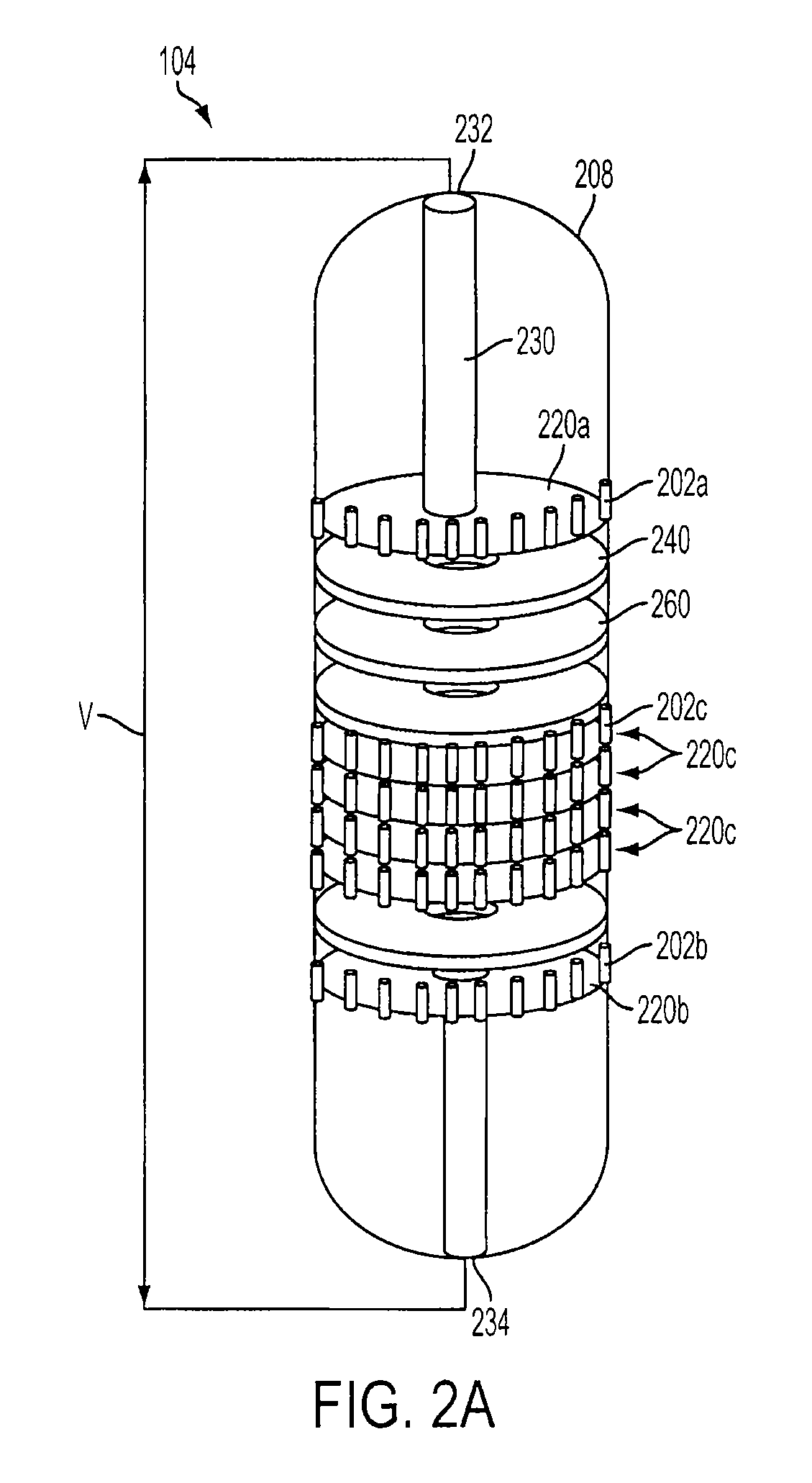
Methods and systems for manufacturing a swallowable sensor device are disclosed. Such a method includes mechanically coupling a plurality of internal components, wherein the plurality of internal components includes a printed circuit board having a plurality of projections extending radially outward. A cavity is filled with a potting material, and the mechanically coupled components are inserted into the cavity. The cavity may be pre-filled with the potting material, or may be filled after the mechanically coupled components have been inserted therein. A distal end of each projection abuts against a wall of the cavity thereby preventing the potting material from covering each distal end. The cavity is sealed with a cap causing the potting material to harden within the sealed cavity to form a housing of the swallowable sensor device, wherein the distal end of each projection is exposed to an external environment of the swallowable sensor device.

Description

BACKGROUND OF THE INVENTION[0001]1. Field of the Invention[0002]The present invention relates to medical diagnostics, and in particular, to swallowable medical diagnostic devices.[0003]2. Background Art[0004]The population of the United States is aging. The first wave of the 78 million “Baby Boomers” is beginning to turn 60 years old. There has been an explosion in diabetes cases, estimated at 194 million cases worldwide today, and predicted to reach 350 million cases by year 2025. Obesity currently affects two thirds of the U.S. population. There is a rising incidence of cardiac problems for women (the number one cause of death for women). Hepatitis C will soon reach epidemic levels, infecting nearly 5 million people, more than the number of people infected with AIDS in the U.S. Thus, simple and easy diagnostic and treatment techniques are needed, especially because many of the diseases that afflict the population are chronic, requiring repeat testing and treatment over time.[0005]...

Claims


Application Information

Patent Timeline
IPC IPC(8): A61B5/04B65D85/38G08C19/16H05K3/00
CPCA61B1/0011Y10T29/49126A61B5/07H05K1/144A61B5/073H05K3/36Y10T29/49124Y10T29/53022Y10T29/4913Y10T29/49117Y10T29/49002Y10T29/49004Y10T29/5313Y10T29/49146A61B1/041Y10T29/53252
Inventor ARNESON, MICHAEL R.BANDY, WILLIAM R.DAVENPORT, ROGER A.POWELL, KEVIN J.SLOAN, MICHAEL C.
Owner INNURVATION
Learn More