
Apparatus and method for wireless energy and/or data transmission between a source device and at least one target device

a wireless energy and/or data transmission technology, applied in the direction of batteries, exchanging data chargers, inductances, etc., can solve the problems of difficult to match the resonant frequencies of the primary and/or secondary circuits to one another, the maintenance of the resonance conditions in the primary and/or secondary circuits is relatively complex, and the complexity of the level of complexity is relatively high, so as to simplify the manufacture of the entire apparatus and facilitate the effect of changing

Inactive Publication Date: 2009-04-02
MAQUET GMBH
View PDF11 Cites 333 Cited by
  • Summary
  • Abstract
  • Description
  • Claims
  • Application Information

AI Technical Summary

Benefits of technology

[0020]In addition, it is advantageous to provide at least two resonant circuits which are each electrically isolated from the secondary circuit and from the respective other circuit. The inductances of the at least two resonant circuits are preferably each in the form of a coil, whose windings are formed as bifilar windings or, in the case of more than two resonant circuits, as n-filar windings. As a result of the bifilar windings or, in the case of n resonant circuits, as a result of the n-filar windings, the coils formed by these windings preferably have the same inductance, with the result that the resonant frequency can be set merely by selecting different capacitances. This is advantageous if the resonant circuits have different resonant frequencies from one another, with the result that the energy transmission between the primary circuit and the secondary circuit is influenced by the resonant circuits with the superimposed resonant frequencies of the resonant circuits or of the resonators.
[0021]It may also be advantageous if the winding of the secondary coil and the winding of a coil forming the inductance of the resonant circuit and / or the winding of the primary coil and the winding of a coil forming the inductance of the resonant circuit can be formed as a bifilar winding. If a plurality of resonant circuits is provided, the windings of the coils of the resonant circuits or the windings of some of the coils of the resonant circuit and the primary winding or the secondary winding can be formed as n-filar windings. The provision of n-filar windings simplifies the manufacture of the entire apparatus. In particular, the inductance of the coils formed by the n-filar windings can easily be changed, in particular doubled, by a plurality of coils being interconnected.

Problems solved by technology

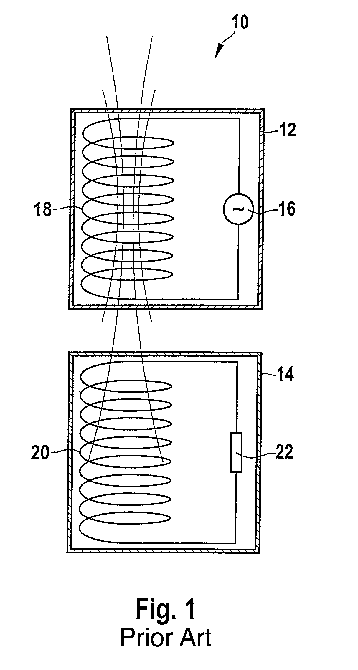
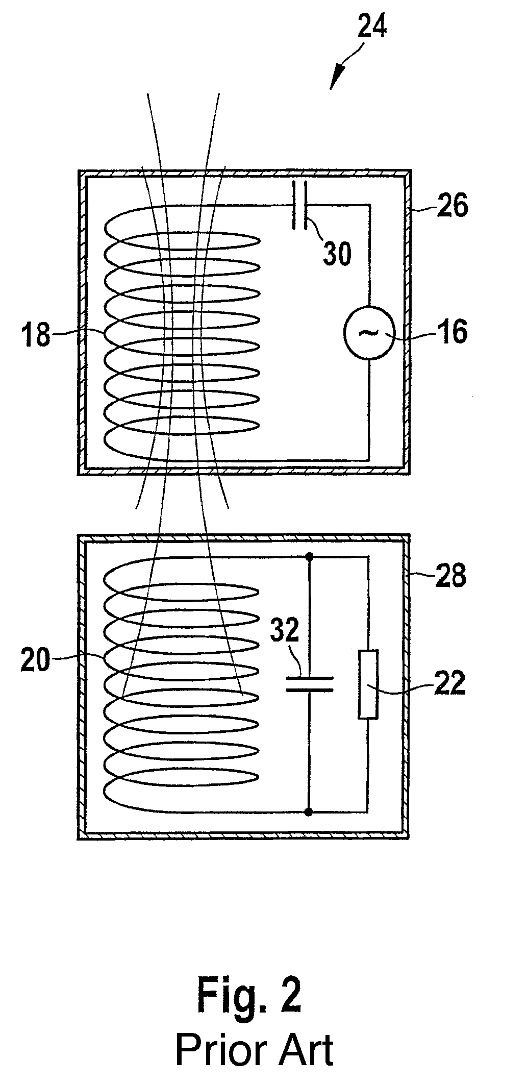
However, in practice it is difficult to match the resonant frequencies of the primary-side resonant circuit and of the secondary-side resonant circuit to one another since the resonance conditions change depending on the state of charge of the rechargeable batteries or depending on the resistance value of the load resistor 22, which changes over the charging cycle.
However, this is associated with a relatively high level complexity.
Overall, maintenance of the resonance conditions in the primary and / or secondary circuit is relatively complex.

Method used


Image

  • Apparatus and method for wireless energy and/or data transmission between a source device and at least one target device
  • Apparatus and method for wireless energy and/or data transmission between a source device and at least one target device
  • Apparatus and method for wireless energy and/or data transmission between a source device and at least one target device

Examples


first embodiment

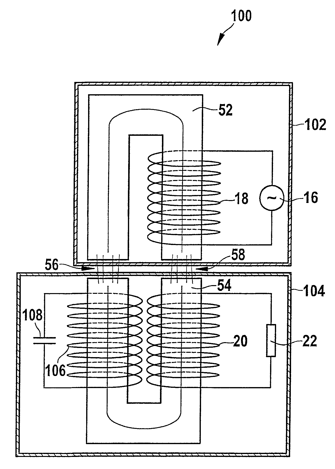
[0031]FIG. 6 illustrates an arrangement 100 for wireless energy and / or data transmission between a source device 102 and a target device 104 in accordance with the invention. The arrangement 100 has a similar design to the known arrangement 46 already described and shown in FIG. 4. Identical elements have the same reference symbols. In addition to the primary-side circuit, which comprises the energy source 16 and the coil 18, the arrangement 100 also has the secondary-side circuit with the secondary coil 20 and with the charging circuit 22 illustrated as a load resistor. The magnet or iron core comprises a first primary-side u-shaped magnet core segment 52, around which the windings of the primary coil 18 are arranged, and a second secondary-side u-shaped magnet core segment 54. The gaps 56, 58 are provided between the magnet core segments 52, 54 in a charging and / or data transmission position of the source device 102 and of the target device 104. In addition, the arrangement 100 ha...

second embodiment

[0032]FIG. 7 illustrates an arrangement 110 for wireless energy and / or data transmission between a source device 112 and a target device 114 in accordance with the invention. The arrangement 110 has a similar design to the arrangement 100 shown in FIG. 6. In contrast to the arrangement 100 shown in FIG. 6, the resonator comprising the coil 106 and the capacitor 108 is arranged physically in the source device 112, with the windings of the coil 106 being arranged around the first magnet core segment 52 of the magnet core.

third embodiment

[0033]FIG. 8 illustrates an arrangement 120 for wireless energy and / or wire transmission between a source device 122 and a target device 124 in accordance with the invention, in which both a primary-side resonator and a secondary-side resonator are provided. A coil 126 and a capacitor 128 are electrically connected to one another and form the secondary-side resonator. A coil 130 and a capacitor 132 are electrically connected to one another to form a circuit and form the primary-side resonator. The windings of the coil 130 and of the primary coil 18 on the source-device side are formed as bifilar windings. In the same way, the windings of the coil 126 and of the secondary coil 20 on the target-device side are formed as a bifilar winding.


PUM


Abstract

The invention relates to an apparatus and a method for wireless energy and / or data transmission between a source device and at least one target device, in which apparatus and method a voltage is induced by at least one primary coil (18), on the source-device side, of at least one primary circuit in at least one secondary coil (20), on the target-device side, of at least one secondary circuit and in at least one coil of at least one resonant circuit, the resonant circuit being arranged so as to be electrically isolated from the primary circuit and from the secondary circuit.

Description

CROSS REFERENCE TO RELATED APPLICATIONS[0001]Applicant hereby claims foreign priority benefits under U.S.C. § 119 from German Patent Application No. 10 2007 041 686.7 filed on Sep. 1, 2007 and German Patent Application No. 10 2007 060 822.2 filed Dec. 18, 2007, the contents of which are incorporated by reference herein.TECHNICAL FIELD[0002]The invention relates to an apparatus and a method for wireless energy and / or data transmission between a source device and at least one target device, in which apparatus and method at least one primary circuit with at least one primary coil, on the source-device side, and at least one secondary circuit with at least one secondary coil, on the target-device side, are provided. In particular, the invention relates to inductive energy transmission between devices or device components for the purpose of charging at least one rechargeable battery arranged in a device or in a device component, such as for the purpose of charging a rechargeable battery ...

Claims


Application Information

Patent Timeline
IPC IPC(8): H02J17/00
CPCH01F38/14H02J5/005H01F2038/143H02J7/00034H02J50/402H02J50/12H02J50/80
Inventor BRUHN, ALFRED
Owner MAQUET GMBH
Learn More