
On-wing combustor cleaning using direct insertion nozzle, wash agent, and procedure

a technology for combustor cleaning and combustor nozzles, applied in the direction of machines/engines, cleaning using liquids, lighting and heating apparatus, etc., can solve the problems of reducing the efficiency of the engine, and reducing the lean blowout margin

Active Publication Date: 2009-04-02
HONEYWELL INT INC
View PDF20 Cites 55 Cited by
  • Summary
  • Abstract
  • Description
  • Claims
  • Application Information

AI Technical Summary

Benefits of technology

[0015]In a further aspect of the present invention, an apparatus for a cleaning a combustor comprises a first spray portion capable of being inserted through an opening of the combustor, the first spray portion...

Problems solved by technology

During the normal operation of the gas turbine engine, environmental contaminants can accumulate on the surfaces of the combustor, reducing engine efficiency.
Additionally, contaminants can gather in the effusion cooling holes, the subsequent effusion hole plugging restricts airflow into the combustor, reducing the lean blowout margin until the gas turbine engine has little or no margin, resulting in uncommanded shutdowns of the gas turbine engine.
Contaminant deposits in the effusion holes can also reduce liner cooling efficiency.
Unfortunately, the abrasive particles can damage the base alloy and may become lodged in cracks or effusion holes during the cleaning process.
Additionally, some engine components include internal passageways, such as effusion holes, which may not be sufficiently cleaned using these methods.
Although this method may remove contaminant buildup from effusion holes, it requires the component to be removed from the engine and immersed in the solution.
For some applications, component removal is a time consuming and costly process.
Although this method may be useful for cleaning some combustors, it may not be suitable for cleaning all combustor configuration types.
For example, the described method may not provide sufficient cleaning to the inner liner of an annular combustor because the cleaning fluid may not adequately contact the surfaces of the inner liner.

Method used


Image

  • On-wing combustor cleaning using direct insertion nozzle, wash agent, and procedure
  • On-wing combustor cleaning using direct insertion nozzle, wash agent, and procedure
  • On-wing combustor cleaning using direct insertion nozzle, wash agent, and procedure

Examples


example 1

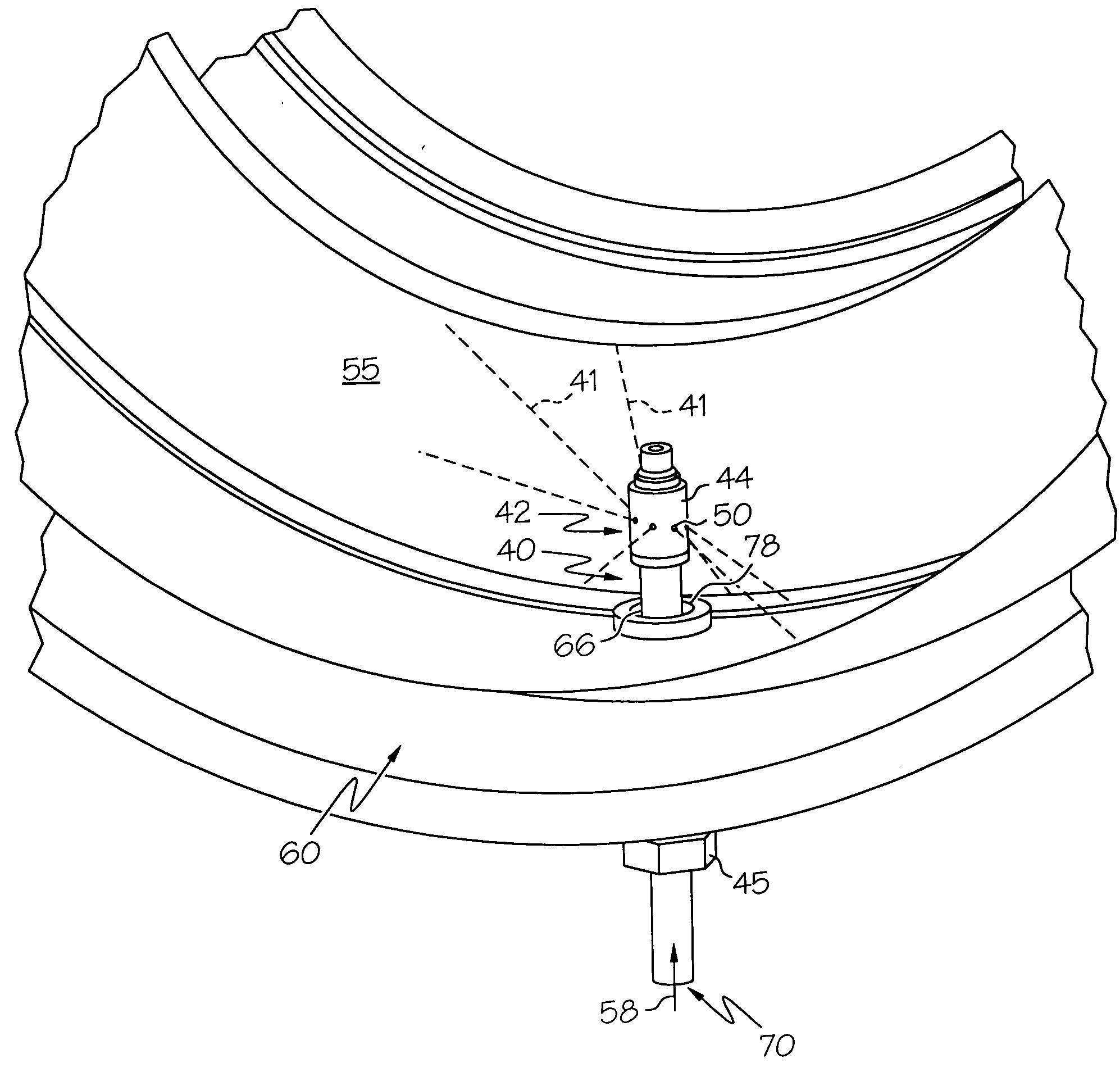
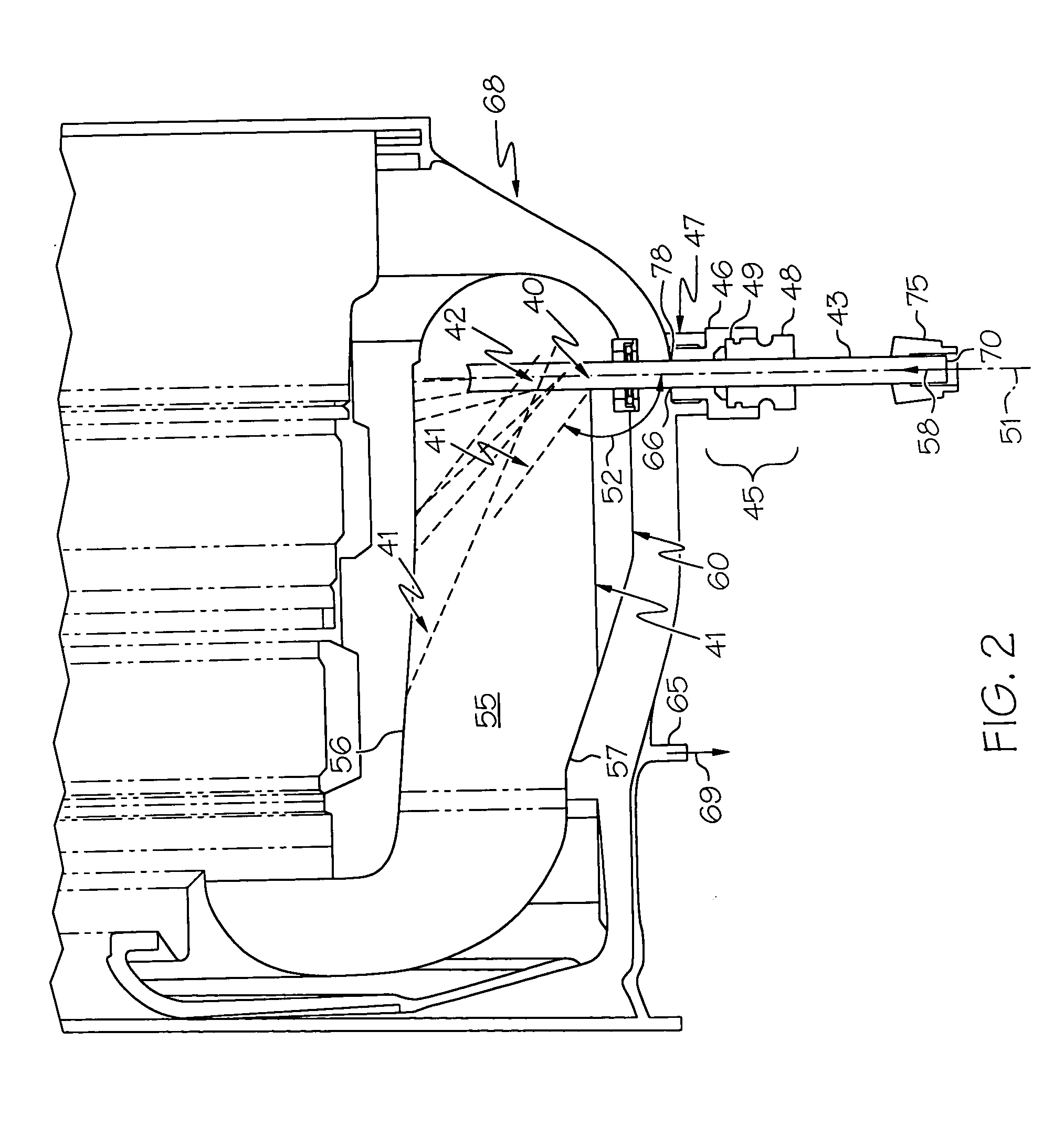
[0053]An annular combustor having two igniter plug bosses was provided, as shown in FIGS. 12a and b. The combustor was about 65 percent plugged. Several completely plugged effusion holes (indicated by arrows in FIG. 12b) were circled for later observation. A nozzle assembly comprising a fixed spray bar was inserted into the first igniter plug boss, as shown in FIG. 2. The nozzle assembly was held in position by an adapter portion comprising two fittings and an o-ring. The receiving aperture of the nozzle assembly was attached to a quick disconnect fluid fitting elbow. The spray portion of the nozzle assembly was manually rotated while ½ gallon of 5% acetic acid was pumped through the nozzle at 60 psi using a pump assembly with a minimum flow rate of ½ GPM. The nozzle assembly was removed from the first igniter plug boss and positioned in the second igniter plug boss. The nozzle was manually rotated while another ½ gallon of 5% acetic acid was pumped through the nozzle at 60 psi usin...


PUM

PropertyMeasurementUnit
Fractionaaaaaaaaaa
Fractionaaaaaaaaaa
Fractionaaaaaaaaaa

Abstract

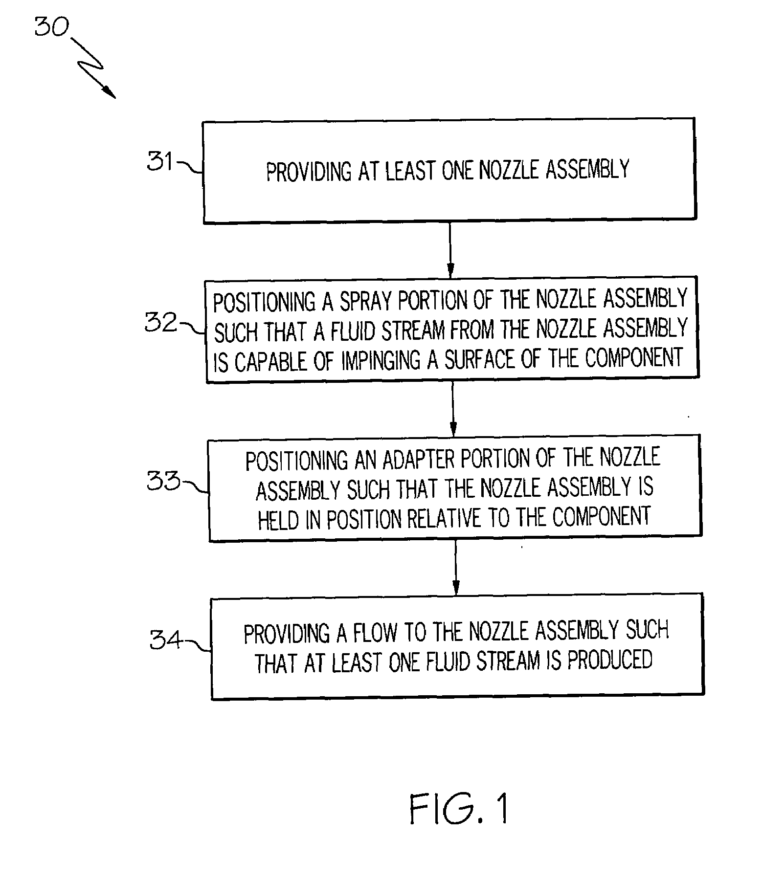
A cleaning method for a combustor comprises positioning a spray portion of a nozzle through an igniter plug boss and spraying an acid solution inside the combustion chamber. The acid solution impinges the inner liner and the outer liner, dissolving contaminant deposits inside the effusion holes. The nozzle can have a second spray portion outside the combustion chamber to provide acid solution to the radially outward surface of the outer liner. After cleaning, distilled water is sprayed through the nozzle to remove the acid solution residue from the combustor. The used acid solution and distilled water can be collected, filtered and pumped through the nozzle to provide a recirculating cleaning / rinsing system.

Description

CROSS-REFERENCE TO RELATED APPLICATION[0001]This application claims the benefit of U.S. Provisional Application Ser. No. 60 / 619,981, which was filed on Oct. 19, 2004, and is incorporated herein by reference.BACKGROUND OF THE INVENTION[0002]The present invention generally relates to methods and apparatus for cleaning components, more particularly, to methods and apparatus for cleaning gas turbine combustors.[0003]A combustor is an important component of a gas turbine engine. Combustors comprise a combustion chamber defined by one or more combustor liners and a combustor dome. One of the more common combustor configuration types used in gas turbine engines, such as auxiliary power units (APU), is an annular combustor. An inner liner, an outer liner and a dome define the combustion chamber of an annular combustor. A mixture of fuel and air is introduced into the combustion chamber where it is ignited to produce combustion gases for a downstream turbine.[0004]Because combustors are expo...

Claims


Application Information

Patent Timeline
IPC IPC(8): B08B9/093
CPCB08B9/00Y02T50/67F23J1/02F01D25/002Y02T50/60
Inventor WOODCOCK, GREGORY O.MAHAR, ROBERT W.TESCH, WILLIAMBONVOULOIR, RICHARD A.SAUNDERS, JOHN C.SCHUELKE, UDO
Owner HONEYWELL INT INC
Learn More